| Author |
 Topic Topic  |
|
|
Geo-Johnny
    
Austria
161 Posts |
 Posted - 10/07/2019 : 13:14:53 Posted - 10/07/2019 : 13:14:53


|
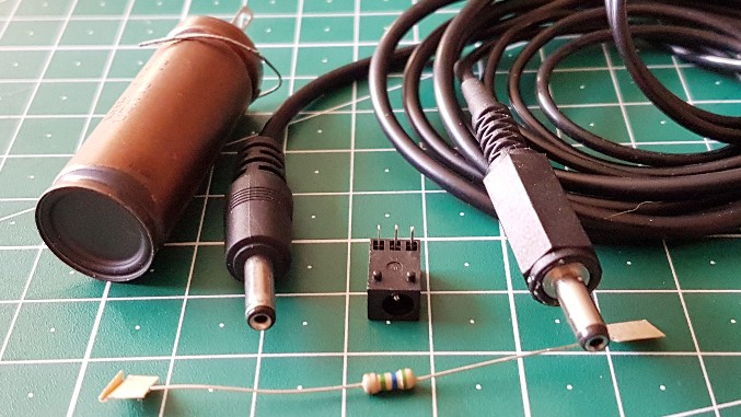
The new version of the GMC500+ is ideal for DIY and experiments thanks to the dual technology of the two counter tubes, the automatic and manual voltage adjustment, the separate calibration option and the separate dead time setting. Inspired by the colleague Stargazer_40 and his wand solution, I have realized a high voltage output for the connection of different counter tubes by means of a 3,5mm hollow plug socket(like the DC jack of old Nokia phones). When connecting an external counter tube, one of the two inner counter tubes is automatically switched off. Ideally, the internal counter tube 1(M4011) should be switched off and its AVA used for the output. After much deliberation, I decided to switch off the internal counter tube 2(SI-3BG) because of the shorter internal cable routing. It is more important to me to set the high voltage manually for the external counter tube itself.
A few components:
High Voltage Output:
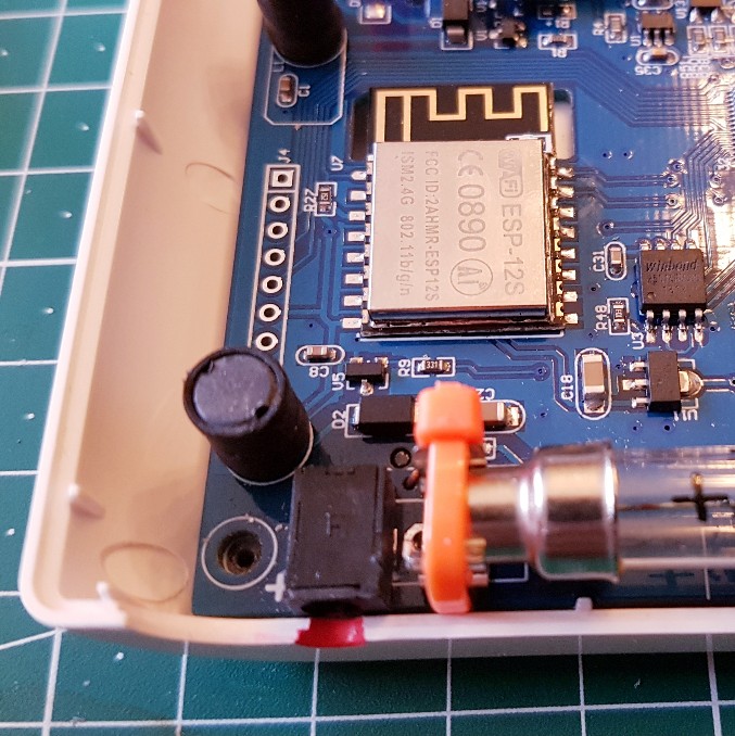
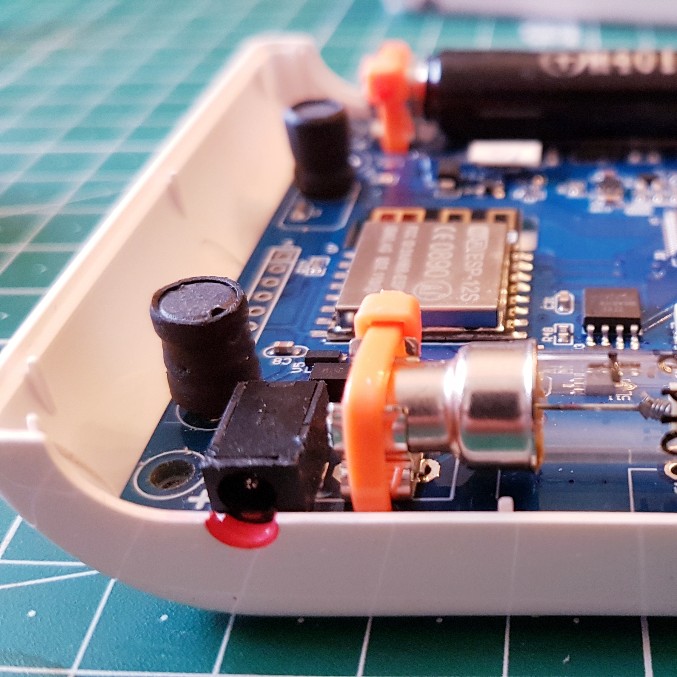
Finished:
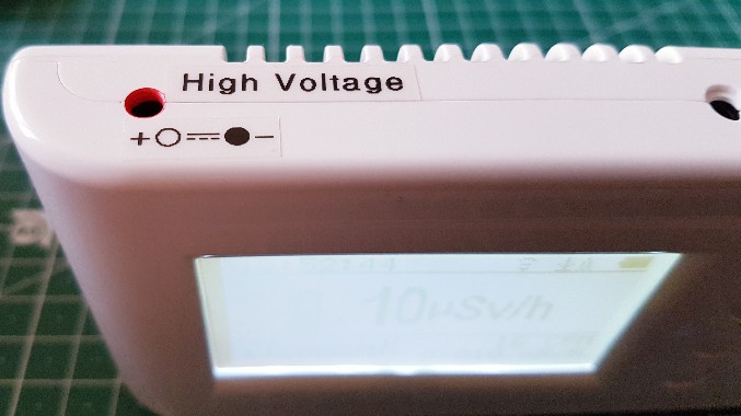
Everything works great. It has already been tested with several counter tubes, only the new LND712 tube shown above is broken. The seller sends me a free replacement. The outer conductor of the coaxial cable is the anode lead and shields the inner counting cathode lead. This saves you a separate shielding.
Sequel follows ...
Edit: The internal anode resistor was not used externally. It is the full high voltage at the output. So each external counter tube needs its own special anode resistor near the anode itself! This is the better solution because each counter tube type needs a different value for the anode resistance. |
Geiger Counters: GMC320+V5 & GMC500+
Geiger Tubes: M4011; SI-3BG; SBT-9; LND712; SBM-20 |
Edited by - Geo-Johnny on 10/07/2019 13:28:19
|
|
| Reply #1
Geo-Johnny
    
Austria
161 Posts |
 Posted - 10/07/2019 : 14:04:43 Posted - 10/07/2019 : 14:04:43


|
| A store and restore function of the user settings in the GMC Data Viewer / Logger Pro would be very desirable for my purposes. So I could save the settings for all external counter tubes in different profiles and restore if necessary with a mouse click for the currently used counter tube. Please support, so build a store and restore function in the programs! It would also help many other users. |
Geiger Counters: GMC320+V5 & GMC500+
Geiger Tubes: M4011; SI-3BG; SBT-9; LND712; SBM-20 |
 |
|
| Reply #2
Stargazer 40
    
USA
431 Posts |
 Posted - 10/07/2019 : 18:27:07 Posted - 10/07/2019 : 18:27:07


|
Very nice. I used a three pin din plug for the connection. The 3.5mm mini plug is much more available. There still is a problem with voltage drop out of plateau region for high counts, but really I think this mod (like my V1 500+) will allow testing many different tubes with a manual measure of voltage. Not convenient, but once you map percentage to voltage it's done.
Like the appliques on the HV warning. :=)
It will make the stock 500+ more expensive, but really we need to get AVA applied to both tubes for constant voltage no matter the CPM. |
Stargazer 40 |
Edited by - Stargazer 40 on 10/07/2019 18:29:02 |
 |
|
| Reply #3
Geo-Johnny
    
Austria
161 Posts |
 Posted - 10/07/2019 : 22:50:49 Posted - 10/07/2019 : 22:50:49


|
| @ Stargazer_40, you are 100% right, a further development of the GMC500+ in relation to the AVA for both counter tubes would be highly recommended and desirable. The manual setting of the high voltage is not a problem for occasional tests, automatically is easier of course. Much more important to me personally would be a store / restore function for the user settings. No matter how the development progresses, it's certainly not my last Geiger counter from GQ Electronics. |
Geiger Counters: GMC320+V5 & GMC500+
Geiger Tubes: M4011; SI-3BG; SBT-9; LND712; SBM-20 |
 |
|
| Reply #4
Stargazer 40
    
USA
431 Posts |
 Posted - 10/08/2019 : 03:56:52 Posted - 10/08/2019 : 03:56:52


|
| The latter they have agreed to pursue. There is always lead time for hardware change, but GQ is very nimble and we can hope. |
Stargazer 40 |
 |
|
| Reply #5
Geo-Johnny
    
Austria
161 Posts |
 Posted - 10/17/2019 : 07:55:11 Posted - 10/17/2019 : 07:55:11


|
Today my replacement LND712 counter tube arrived. Immediately I connected it to the GMC500+ and tested it. Everything works perfectly. Nice would be a separate calibration menu for calibration, dead time and voltage setting for an external counter tube. Ok, you can not have everything, so I'm going to make the GMC600+ myself a Christmas present.
Edit: And here is my Calibrationsdaten for the LND712 counter tube externally on the GMC500+ as counter tube 2 ...
Tube Voltage: ~500V = 60%
Calibration: 525CPM = 4,85uSv/h
Dead Time: 90uS |
Geiger Counters: GMC320+V5 & GMC500+
Geiger Tubes: M4011; SI-3BG; SBT-9; LND712; SBM-20 |
Edited by - Geo-Johnny on 10/17/2019 08:36:35 |
 |
|
| Reply #6
Stargazer 40
    
USA
431 Posts |
 Posted - 10/17/2019 : 14:29:33 Posted - 10/17/2019 : 14:29:33


|
| Thanks Geo-Johnny for the calibration data. I'll compare with my LND712 and see how I faired on these two points. |
Stargazer 40 |
 |
|
| Reply #7
Damien68
    
France
780 Posts |
 Posted - 10/17/2019 : 23:31:54 Posted - 10/17/2019 : 23:31:54


|
often these cables that you use are not coaxial cables but consists of 2 independent wires surrounded by a sheath.
In all cases it must work but it must still remain sensitive to electromagnetic disturbances.
Especially at the level of the tube, if for example you approach your hand to the cathode tube this must create disturbances.
That is why the recommended connection of the LND-712 and all alpha window tubes in general is not the same as for a classic tube.
See datasheet:
https://www.sparkfun.com/datasheets/Components/General/LND-712-Geiger-Tube.pdf
The detection is not done on the cathode current sensing but on the anode current sensing through a splited anode resistor, and the cathode is directly connected to the ground.
We could try to make the same connection using 3 outputs (Ground, HV, Signal) and a splited anode resistor + a high voltage decoupling capacitor.
GND is PCB Ground
HV is M4011 or tube 2 Anode connection (before anode resistor)
Signal is M4011 or tube 2 Cathode connection
The pulse will be reversed but it should not disturb, But I do not think it will work because in this configuration the detection is sensitive to the HV generator noise.
If the HV power supply is too noisy (not regulated enough) it will create detections. in my opinion it will be the case.
When I have time, I will try to do it to see what it gives.
The best I think is to do as you did but to keep a cable short enough |
Mastery is acquired by studying, with it everything becomes simple |
Edited by - Damien68 on 10/18/2019 00:07:21 |
 |
|
| Reply #8
Geo-Johnny
    
Austria
161 Posts |
 Posted - 10/18/2019 : 00:52:29 Posted - 10/18/2019 : 00:52:29


|
@ Stargazer_40, my calibration values are not exact. These are values that can easily be set on the device itself in mobile use, because the CPM value can only be set in hundreds of steps. For a very precise setting, you must calibrate the values via the data logger via the PC. But with about 3 to 5cm distance of the source to the counter tube, these are my values sufficiently accurate. Therefore, I wish for mobile use a small app for the smartphone, with which you can set or synchronize the calibration, the dead time, the counter tube high voltage and the time.
@ Damien68, I used the shield for the anode side and the inner conductor for the counting cathode. Even with about 80cm cable, I have no electromagnetic interference, which affect the count (the smartphone is at a distance of 10cm next to the cable). I soldered the 10MOhm anode resistor directly to the plug of the counter tube. It works ... |
Geiger Counters: GMC320+V5 & GMC500+
Geiger Tubes: M4011; SI-3BG; SBT-9; LND712; SBM-20 |
Edited by - Geo-Johnny on 10/18/2019 01:06:22 |
 |
|
| Reply #9
Damien68
    
France
780 Posts |
 Posted - 10/18/2019 : 01:41:22 Posted - 10/18/2019 : 01:41:22


|
@Geo-Johnny
is OK and reliable,
Smartphone is not a problem because his frequency is high and cutted by filter.
Many switching mode power supply or other can be.
But there is just to be careful though.
We can make some test with the foolowing unit for 23€:
https://www.amazon.fr/Sourcing4U-Executioner-Mosquito-Swatter-Zapper/dp/B003TT3GDC/ref=sr_1_1
Image Insert:

112666 bytes
image is from Amazon site.
This make hard noise around GM tube pulses bandwith
for example if i aproche it near my GMC-500+ this disturb it strongly.
This is normal and not critical, and it certainly do for all similar counter of the market. But is in this case a good test to know about EMI immunity
and a good device to kick the bugs :) |
Mastery is acquired by studying, with it everything becomes simple |
Edited by - Damien68 on 10/18/2019 03:28:12 |
 |
|
| Reply #10
Geo-Johnny
    
Austria
161 Posts |
 Posted - 10/18/2019 : 05:35:38 Posted - 10/18/2019 : 05:35:38


|
Of course, such devices disturb the Geiger counter, of course. But you could use the high voltage part of such a killing machine for a DIY Geiger counter, especially since these things are cheap to buy.
Back to the topic ... I am eagerly waiting for any small smartphone app for the GQ Geiger counters. Unfortunately, I can not program it myself, so I hope that this is a programmer read and finally published a mobile help for the GQ GMCs. |
Geiger Counters: GMC320+V5 & GMC500+
Geiger Tubes: M4011; SI-3BG; SBT-9; LND712; SBM-20 |
 |
|
| Reply #11
Gelu
 
Romania
18 Posts |
 Posted - 10/18/2019 : 06:32:26 Posted - 10/18/2019 : 06:32:26


|
quote:
Originally posted by Damien68
often these cables that you use are not coaxial cables but consists of 2 independent wires surrounded by a sheath.
In all cases it must work but it must still remain sensitive to electromagnetic disturbances.
Especially at the level of the tube, if for example you approach your hand to the cathode tube this must create disturbances.
That is why the recommended connection of the LND-712 and all alpha window tubes in general is not the same as for a classic tube.
See datasheet:
https://www.sparkfun.com/datasheets/Components/General/LND-712-Geiger-Tube.pdf
The detection is not done on the cathode current sensing but on the anode current sensing through a splited anode resistor, and the cathode is directly connected to the ground.
We could try to make the same connection using 3 outputs (Ground, HV, Signal) and a splited anode resistor + a high voltage decoupling capacitor.
GND is PCB Ground
HV is M4011 or tube 2 Anode connection (before anode resistor)
Signal is M4011 or tube 2 Cathode connection
The pulse will be reversed but it should not disturb, But I do not think it will work because in this configuration the detection is sensitive to the HV generator noise.
If the HV power supply is too noisy (not regulated enough) it will create detections. in my opinion it will be the case.
When I have time, I will try to do it to see what it gives.
The best I think is to do as you did but to keep a cable short enough
Hi, with my apologies, I try to express my own opinion about what Damien68 expressed. For the measurement of Alpha, Beta, Gamma, these tubes are constructed specifically to be snsibile for the corresponding wavelengths. The signal is recommended, as a rule, to reap the Katod with a resistance of 100KOhm to GND. One primary reason is to have a maximum signal/noise gain. The second reason is to protect the circuits that process the useful signal from high HV values. It is true that it works with very small currents but it is about the high potential of tension. A third reason would lose the gain signal/noise.
I agree with Damien68, when he said that I need a coaxial cable with the third shield. I argue this, by the fact that the third shield binds to a single point of GND, preferably to the device, to cancel the loop against the GND. |
 |
|
| Reply #12
Gelu
 
Romania
18 Posts |
 Posted - 10/18/2019 : 06:52:02 Posted - 10/18/2019 : 06:52:02


|
quote:
Originally posted by Damien68
often these cables that you use are not coaxial cables but consists of 2 independent wires surrounded by a sheath.
In all cases it must work but it must still remain sensitive to electromagnetic disturbances.
Especially at the level of the tube, if for example you approach your hand to the cathode tube this must create disturbances.
That is why the recommended connection of the LND-712 and all alpha window tubes in general is not the same as for a classic tube.
See datasheet:
https://www.sparkfun.com/datasheets/Components/General/LND-712-Geiger-Tube.pdf
The detection is not done on the cathode current sensing but on the anode current sensing through a splited anode resistor, and the cathode is directly connected to the ground.
We could try to make the same connection using 3 outputs (Ground, HV, Signal) and a splited anode resistor + a high voltage decoupling capacitor.
GND is PCB Ground
HV is M4011 or tube 2 Anode connection (before anode resistor)
Signal is M4011 or tube 2 Cathode connection
The pulse will be reversed but it should not disturb, But I do not think it will work because in this configuration the detection is sensitive to the HV generator noise.
If the HV power supply is too noisy (not regulated enough) it will create detections. in my opinion it will be the case.
When I have time, I will try to do it to see what it gives.
The best I think is to do as you did but to keep a cable short enough
More wish to make a remark, never send through a high-value HV cable, even if it has shieling, or uncoupling capacitiva, to such types of devices. As an example, there are appliances that read high Gamma fields, they use complex detectors, which receive low DC voltage values, to feed the Power module of HV which is very close to the detector (Geiger Tube). And the signal picked off the Katod, is modulated in the current and sent back to the monitoring point. It prefers modulation in the current under different standards of signal issuance to suppress the noise. |
 |
|
| Reply #13
Damien68
    
France
780 Posts |
 Posted - 10/18/2019 : 13:21:41 Posted - 10/18/2019 : 13:21:41


|
@Geo-Johnny
I made my app under windows, I know that Android supports natively the USB/CDC class necessary to communicate with the counter there is no software particular difficulty. What GQ do?
after if we connect a counter to a smartphone, I'm not sure if it's really feasible.
There are normaly hardware protocols to follow in USB connection, the current available on the USB port of the smartphone in OTG mode is not necessarily compatible with the current management done in the counter unit, mostly if counter try to charge his own battery.
Today, all pc can provide 500mA on their USB port, for smartphone it's less sure.
In fact the feasibility is not necessarily obvious,there may be hardware issues.
|
Mastery is acquired by studying, with it everything becomes simple |
Edited by - Damien68 on 10/18/2019 13:37:41 |
 |
|
| Reply #14
Geo-Johnny
    
Austria
161 Posts |
 Posted - 10/18/2019 : 13:37:25 Posted - 10/18/2019 : 13:37:25


|
| No idea. In any case, we first have to find someone who can program an app for Android and / or IOS. Then you can decide whether the app should connect to the GMC via USB, Wifi or both. |
Geiger Counters: GMC320+V5 & GMC500+
Geiger Tubes: M4011; SI-3BG; SBT-9; LND712; SBM-20 |
 |
|
| Reply #15
Damien68
    
France
780 Posts |
 Posted - 10/18/2019 : 13:46:27 Posted - 10/18/2019 : 13:46:27


|
| it's stupid I know someone who already mastered all this, he programs apps on tablet for wifi devices that I made, but I can not ask him that. |
Mastery is acquired by studying, with it everything becomes simple |
 |
|
| Reply #16
Stargazer 40
    
USA
431 Posts |
 Posted - 10/18/2019 : 15:54:02 Posted - 10/18/2019 : 15:54:02


|
| Gamma sensitivity of LND712 is 1080 CPM according to LND. That's for a Co60 source which is mostly higher energy gammas. I normally go with their published numbers. |
Stargazer 40 |
 |
|
| Reply #17
Geo-Johnny
    
Austria
161 Posts |
 Posted - 10/18/2019 : 23:02:17 Posted - 10/18/2019 : 23:02:17


|
| I'm generally convinced that the WiFi module should be exploited much more in the newer GMC500 and GMC600. Just sending the data to the world map server is not enough. If you are already in the same network via a router or hotspot connection, you should use this immediately for a data and control exchange, as the function for the world map server is not affected. Therefore, it would be important for smartphones, tablets and computers to program software that can communicate with the GMC via Wifi. That would make the GQ GMCs much more valuable. The older models will not be enough room for the necessary code in the firmware, but with the newer GMCs should be possible without problems. |
Geiger Counters: GMC320+V5 & GMC500+
Geiger Tubes: M4011; SI-3BG; SBT-9; LND712; SBM-20 |
 |
|
| Reply #18
Damien68
    
France
780 Posts |
 Posted - 10/19/2019 : 01:02:55 Posted - 10/19/2019 : 01:02:55


|
You're right Geo-Johnny, I did not think about that, to communicate via wifi between a smartphone and a counter, it's necessary that the firmware of the counter is made for that.
In fact, as it's, it can't work.
ESP-12s inside the counter is a ESP-8266, is a cheep version of the ESP-32 and dedicated to IOT device but without Bluetooth. It would have been ideal to can have bluetooth connection. |
Mastery is acquired by studying, with it everything becomes simple |
 |
|
| Reply #19
Geo-Johnny
    
Austria
161 Posts |
 Posted - 10/20/2019 : 08:54:37 Posted - 10/20/2019 : 08:54:37


|
| No, no, you can easily let the Wifi module work as a server and access the Geiger counter via a TCP port. But this must be set up in the firmware of the Geiger counter. If the Geiger counter sends data via a smartphone hotspot to the world map server, it is already connected to its own WLAN and gets a unique internal IP address. Thus, a smartphone app would have access to the WiFi Geiger counter module. Bluetooth is another story and meaningless if the wireless connection is already available anyway. Bluetooth is more for children, because the range is just a stone's throw. WiFi is strong enough and above all already installed and in operation. So it's just a software matter. |
Geiger Counters: GMC320+V5 & GMC500+
Geiger Tubes: M4011; SI-3BG; SBT-9; LND712; SBM-20 |
 |
|
| Reply #20
ZLM
    
1271 Posts |
 Posted - 10/20/2019 : 20:09:20 Posted - 10/20/2019 : 20:09:20


|
| I agree with Geo-Johnny s point. The Wifi is a much advanced connection than bluetooth. The bluetooth only for short distance communication. |
 |
|
| Reply #21
ullix
    
Germany
1241 Posts |
 Posted - 10/20/2019 : 22:38:49 Posted - 10/20/2019 : 22:38:49


|
@ZLM:
quote:
The bluetooth only for short distance communication.
Really?
WiFi goes up 100m. Bluetooth goes up to 100m. Which of the two is shorter?
|
 |
|
| Reply #22
Geo-Johnny
    
Austria
161 Posts |
 Posted - 10/20/2019 : 23:33:40 Posted - 10/20/2019 : 23:33:40


|
Bluetooth   
And why should one convert to Bluetooth, if a good WiFi module is already installed and in use? Unfortunately, only a small function is used at the moment, the module itself offers much more potential. |
Geiger Counters: GMC320+V5 & GMC500+
Geiger Tubes: M4011; SI-3BG; SBT-9; LND712; SBM-20 |
 |
|
| Reply #23
Damien68
    
France
780 Posts |
 Posted - 10/21/2019 : 06:30:25 Posted - 10/21/2019 : 06:30:25


|
@Geo-Johnny:
my god, I'm over 50, I withdraw what I said about Bluetooth, it's true that it go no more far than a baby park :-)
@ullix:
Bluetooth Class 1 is +20 dBm (100mW) RF output power and can be received at 100m
Most android smartphones and most Bluetooth devices are Bluetooth Class 2 or 3 and can therefore be received between 1 and 10m
For iphones I do not know exactly but Bluetooth Class 1 is outside his field of application and is very rarely used
h**p://bluetoothinsight.blogspot.com/2008/01/bluetooth-power-classes.html
Wifi vs Bluetooth, it depends on the applications, but it is true that we are not there to make a specification.
|
Mastery is acquired by studying, with it everything becomes simple |
Edited by - Damien68 on 10/21/2019 07:45:13 |
 |
|
| Reply #24
Geo-Johnny
    
Austria
161 Posts |
 Posted - 10/21/2019 : 09:12:25 Posted - 10/21/2019 : 09:12:25


|
quote:
Originally posted by Damien68
@Geo-Johnny:
my god, I'm over 50, ...
Welcome to the club, i am 58+.
And now the end with the Bluetooth discussion. Bluetooth is only for kids to listen to music and play games.
We need a good app on the smartphones for the GMCs, thats it. |
Geiger Counters: GMC320+V5 & GMC500+
Geiger Tubes: M4011; SI-3BG; SBT-9; LND712; SBM-20 |
 |
|
| Reply #25
Stargazer 40
    
USA
431 Posts |
 Posted - 10/21/2019 : 13:11:58 Posted - 10/21/2019 : 13:11:58


|
I have two HVAC thermostats that I get readings and control heat, ac, and blower with a phone app. The thermostats connect to my wifi and the phone app picks up data from the internet. The thermostat maker acts as server and I pay a small fee for each per year. I like the local, internet free Bluetooth approach that works between my Fitbit and phone app, but also like getting readings across the internet when not at home from my thermostats (and controlling them).
As a parallel my CDV-717 ionization chamber survey meter allows the base to be separated from the meter with a 25 foot cable. This allows the detector to be placed outside a shielded area to monitor activity without exposure. I like that aspect of remote measurement and think that certainly would likely be in the 1-10m range making Bluetooth viable. |
Stargazer 40 |
Edited by - Stargazer 40 on 10/21/2019 13:53:16 |
 |
|
| Reply #26
Damien68
    
France
780 Posts |
 Posted - 10/21/2019 : 23:34:56 Posted - 10/21/2019 : 23:34:56


|
| if there are containment walls, it can drastically reduce the range of wifi and bluetooth. |
Mastery is acquired by studying, with it everything becomes simple |
 |
|
| Reply #27
ullix
    
Germany
1241 Posts |
 Posted - 10/22/2019 : 01:46:22 Posted - 10/22/2019 : 01:46:22


|
As Damien has already pointed out, there are multiple classes of Bluetooth, which basically determine the energy consumed by the device. And lastly the power available to the device determines the range.
So it is not the technology per se, but the design decision, which determines range. Both technologies are equal in potential(!) range. The lower range of certain devices is by design, not by technical possibility!
WiFi power can also be restricted by design, and further might be impacted by the legal situation, permitting power only within certain limits.
Confusing the matter, Bluetooth is available as the "Classic" Bluetooth, or as the "BLE" (Bluetooth Low Energy, BT version 4).
The Classic is more suited for a steady stream of data (like music sent to earphones), while BLE more to chunks of data. A Geiger counter application is suited for BLE.
If low energy consumption - like wanting long lasting batteries in a mobile Geiger counter - is a wish, you want to go BLE, and also limit power consumption, hence thereby also limiting range.
But programming BLE is a whole lot more complicated than either classic BT or WiFi. GeigerLog can communicate with devices by WiFi; it is easy and actually is already implemented.
I am now working on a project coupling GeigerLog to a BLE device. Well, that is a real challenge...
|
 |
|
| Reply #28
Damien68
    
France
780 Posts |
 Posted - 10/22/2019 : 07:05:01 Posted - 10/22/2019 : 07:05:01


|
Hi Ullix, welcom to BLE world, BLE is one of my specialties too (hardware in my case and low level device chipset software).
as you say it is a challenge, there is a lot of things to assimilate. With my colleague (for the software) we had to put 10 months to release our first complete system from scratch (home automation) .
As you say BLE is no worse of Wifi, and largly better for low bitrate devices.
BLE having a much narrower bandwidth, his receiver have therefore much more sensitive nature, and for the same power of émission, it carry therefore more far.
The difference in receiver sensitivity between the two (Wifi(bgn) vs Blutooth 4) is about 13 dB this is a power ratio of 20. it marks a first difference.
the principle of BLE is to spend time to wake up and sleep synchronized with the access point. after connected, each device has a periodic time slot during which it must be woken, otherwise he can sleep. During sleep time is totaly frozen, only a wake up timer remain active. It is the first fundamental principle of BLE
So keep connection active with wifi draw minimum of 70 mA on battery as long as the connection is active.
With the Blutooth, it is more arbitrary and parametrable.
Some devices powered with 220mAh coin cell maintain an open connection up to 3 months this gives an average current of 0.3 mA (200 time less than Wifi)
Other Bluetooth home automation devices can hold up to 10 years on the same 220 mAh battery, but they do not make physical connection and just send advertising
It marks a second difference.
Afterwards, if a device is not connected and is trying to connect, then it consumes a lot more, but, less than Wifi. that's why in general you have to press a button to make a connection request.
BLE data flow is limited, his data packets are limited to maximum of 27 or 251 Bytes (depending on the BLE version)
But it's true that BLE seems optimum for a connection between a meter and a phone.
But if you want for example multiple simultanous opened connections (many devices connected to the meter), with Wifi you can have many sockets opened in same time, with BLE this is not possible unless if it's the meter that act server, but it's becoming perverted.
With lasts versions of BLE you can share device with multiples server, but limited to only one connection active.
Otherwise, to return to the USB connection, I did a quick test by conecting a 500+ on the USB connector of a Nexus 5X with a USB Ampere-meter / volt-meter.
During my tests, at boot time the meter has to consume up to 150mA on the USB port of the phone, after boot it consumes less.
150mA for some telephones can be already too much, I can not say too much whether it is correct or not, but I do not feel it.
For a PC connection, this is not a problem |
Mastery is acquired by studying, with it everything becomes simple |
Edited by - Damien68 on 10/22/2019 07:43:20 |
 |
|
| Reply #29
ullix
    
Germany
1241 Posts |
 Posted - 10/22/2019 : 23:26:54 Posted - 10/22/2019 : 23:26:54


|
@Damien: good to know what you are up to! Would you mind if I contacted you when I have some BLE questions?
|
 |
|
| Reply #30
Damien68
    
France
780 Posts |
 Posted - 11/12/2019 : 13:08:58 Posted - 11/12/2019 : 13:08:58


|
@Geo-Johnny:
About LND-712 (I just ordered one in germany), why we don't put the tube in a lead pipe, this would reduce the background noise of the tube, and should not affect the sensitivity of the tube in front of its window.
it could make it possible to increase the Signal / Noise ratio in case we want to measure small levels of radiation. I'll do tests when I get it
Also we could place a complete wand like the Stargazer40 one in a lead tube, this in the same way guarantee the necessary cathode electrical insulation.
Image Insert:
112074 bytes |
Mastery is acquired by studying, with it everything becomes simple |
Edited by - Damien68 on 11/12/2019 13:35:37 |
 |
|
| Reply #31
Geo-Johnny
    
Austria
161 Posts |
 Posted - 11/12/2019 : 14:05:18 Posted - 11/12/2019 : 14:05:18


|
@Damien68
I already had the idea with the lead pipe. But I wanted to make it movable and changeable. A lead pipe and an aluminum pipe. Then you can filter out with aluminum beta rays and with the lead pipe the background radiation. For the front window, I've considered the same thing with removable discs. |
Geiger Counters: GMC320+V5 & GMC500+
Geiger Tubes: M4011; SI-3BG; SBT-9; LND712; SBM-20 |
 |
|
| Reply #32
nonus
  
38 Posts |
 Posted - 06/14/2024 : 01:41:44 Posted - 06/14/2024 : 01:41:44


|
How to properly connect an external gm tube via a DC 3.5 mm connector? Where to solder the cathode and anode?
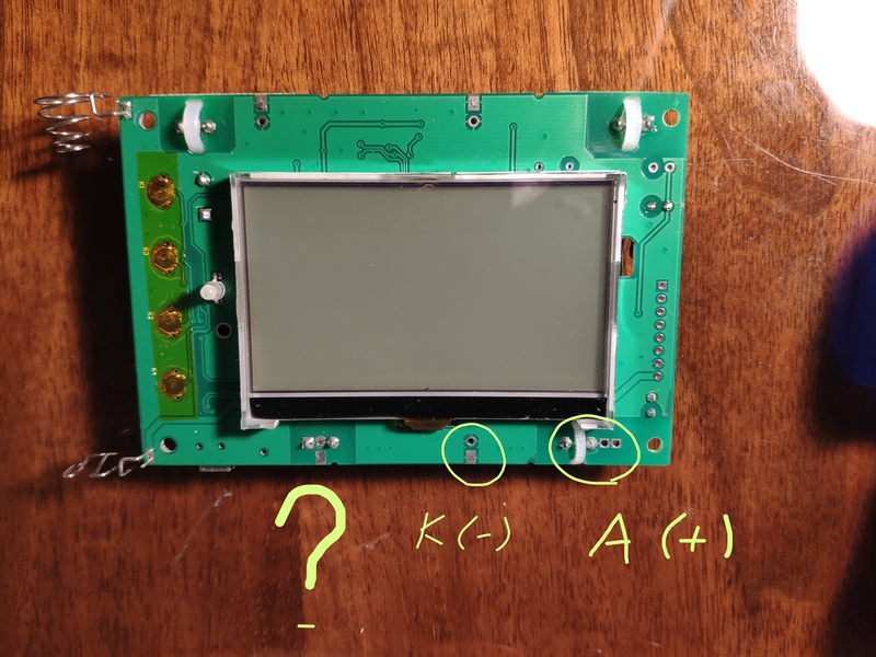 |
Edited by - nonus on 06/14/2024 01:45:31 |
 |
|
| Reply #33
EmfDev
    
2392 Posts |
 Posted - 06/18/2024 : 12:19:56 Posted - 06/18/2024 : 12:19:56


|
Orange is - terminal. Middle is nothing i think.
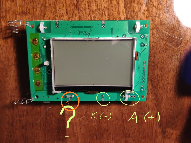 |
 |
|
| Reply #34
nonus
  
38 Posts |
 Posted - 06/19/2024 : 05:03:05 Posted - 06/19/2024 : 05:03:05


|
| Do I need to remove the si-3bg tube if I connect an external tube? The author of the first post wrote that there is automatic switching. I'll try connecting a series of tubes soon. |
 |
|
| Reply #35
EmfDev
    
2392 Posts |
 Posted - 06/21/2024 : 10:22:37 Posted - 06/21/2024 : 10:22:37


|
| Support said it should be ok to connect them in parallel. |
 |
|
| Reply #36
ullix
    
Germany
1241 Posts |
 Posted - 06/21/2024 : 11:07:22 Posted - 06/21/2024 : 11:07:22


|
The 2nd tube has an impact on the 1st only if the 2nd tube draws any current due to registering counts. This would lower the Anode Voltage, and could result in depriving the 1st tube of sufficient voltage. But, since the 2nd tube is so very in-sensitive, it will barely ever register any counts, and thus has almost never an effect on the first tube.
However, since you are experimenting I would want to start with a clean plate, and I would remove the 2nd tube!
Here is a link to a post of mine in this forum done many years ago:
https://www.gqelectronicsllc.com/forum/topic.asp?TOPIC_ID=4571
It shows how easy it is to connect foreign tubes to a GMC counter.
There is one catch: The data are VERY BADLY influenced by the capacitance of the leads to the tube. In my case these were ordinary lab leads, but they were spaced apart widely to minimize capacitance. This helped. When you use a cable holding both leads side-by-side you may get a problem!
See an example for the capacitance effect in this forum post:
https://www.gqelectronicsllc.com/forum/topic.asp?TOPIC_ID=9518
in particular look into Reply#10.
You can test the quality of your setup by applying the Poisson test to recorded data. My software GeigerLog can do that
https://sourceforge.net/projects/geigerlog/ |
 |
|
| Reply #37
nonus
  
38 Posts |
 Posted - 06/21/2024 : 18:32:31 Posted - 06/21/2024 : 18:32:31


|
EmfDev, ullix thanks for the info. On the local market, mica sensors are relatively inexpensive, so I became curious to try new tubes that detect alpha radiation. I ordered sbt-10, sbt-11, sbt-9 and will try it soon. There are also SBT-7 and SBT-13 tubes, but I don’t know how interesting they are.
Update:
External tube SBT-11A, one anode (resistor ~5 MOm)
Stock settings for #2 tube si-3bg (removed)
Source radiation smoke detector (americium 241)
https://youtu.be/F6GpvwKb0ps
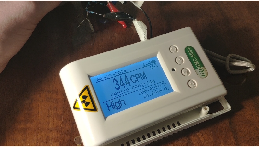
External tube SBT-10, one anode (resistor ~1 MOm)
Stock settings for #2 tube si-3bg (removed)
Source radiation smoke detector (americium 241)
https://youtu.be/3n_kKAavm60
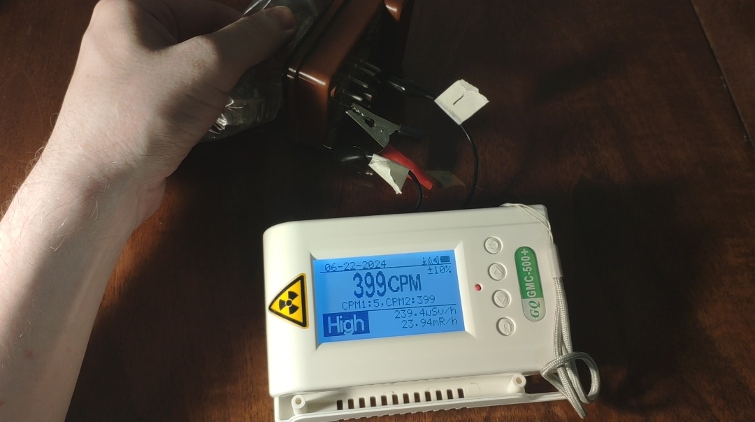
External tube SBM-20-1 (resistor ~5 MOm)
Stock settings for #2 tube si-3bg (removed)
Source radiation smoke detector (americium 241)
https://youtu.be/3SuhFecLCxU
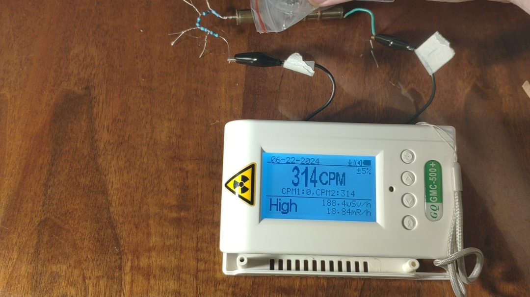
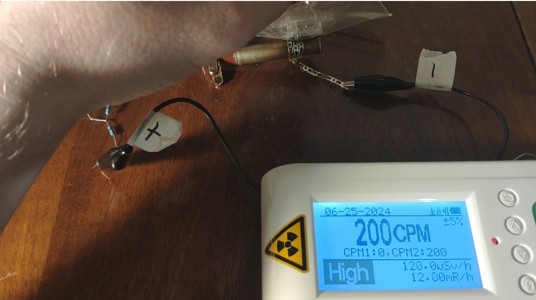
External tube SBT-9 (resistor ~9 MOm)
Stock settings for #2 tube si-3bg (removed)
Source radiation smoke detector (americium 241)
https://youtu.be/BICJ8raOsIo
|
Edited by - nonus on 06/28/2024 00:26:52 |
 |
|
| Reply #38
ullix
    
Germany
1241 Posts |
 Posted - 06/23/2024 : 23:12:46 Posted - 06/23/2024 : 23:12:46


|
Looks good so far!
Don't forget the Poisson check to verify proper counting! |
 |
|
| Reply #39
EmfDev
    
2392 Posts |
 Posted - 06/25/2024 : 09:55:03 Posted - 06/25/2024 : 09:55:03


|
| Did you specifically choose tube 2 on the tube settings? |
 |
|
| Reply #40
nonus
  
38 Posts |
 Posted - 06/25/2024 : 11:07:20 Posted - 06/25/2024 : 11:07:20


|
Yes. I chose tube #2, so tube #1 (SBM-20-1) is not used, but it is physically connected to the board.
Update:
New tubes have arrived...
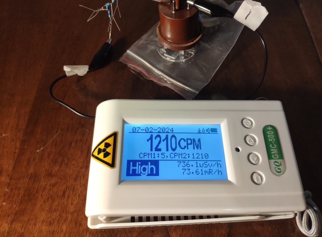
External tube SBT-13 (resistor ~5 MOm)
Stock settings for #2 tube si-3bg (removed)
Source radiation smoke detector (americium 241)
https://youtu.be/gZBlUvx07fs
External tube Si-8B (resistor ~5 MOm)
Stock settings for #2 tube si-3bg (removed)
Source radiation smoke detector (americium 241)
https://youtu.be/gLEXjRqNL14
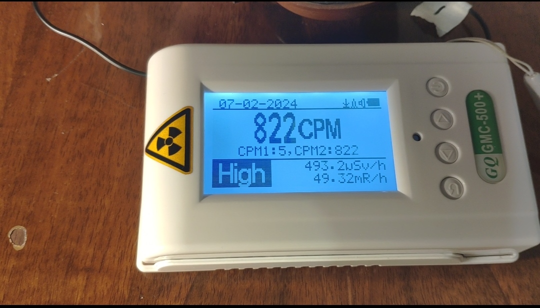
External tube SBT-7 (resistor ~5 MOm)
Stock settings for #2 tube si-3bg (removed)
Source radiation smoke detector (americium 241)
https://youtu.be/IApKep5fAFA?si=MgJtVk3tRRwYldQr
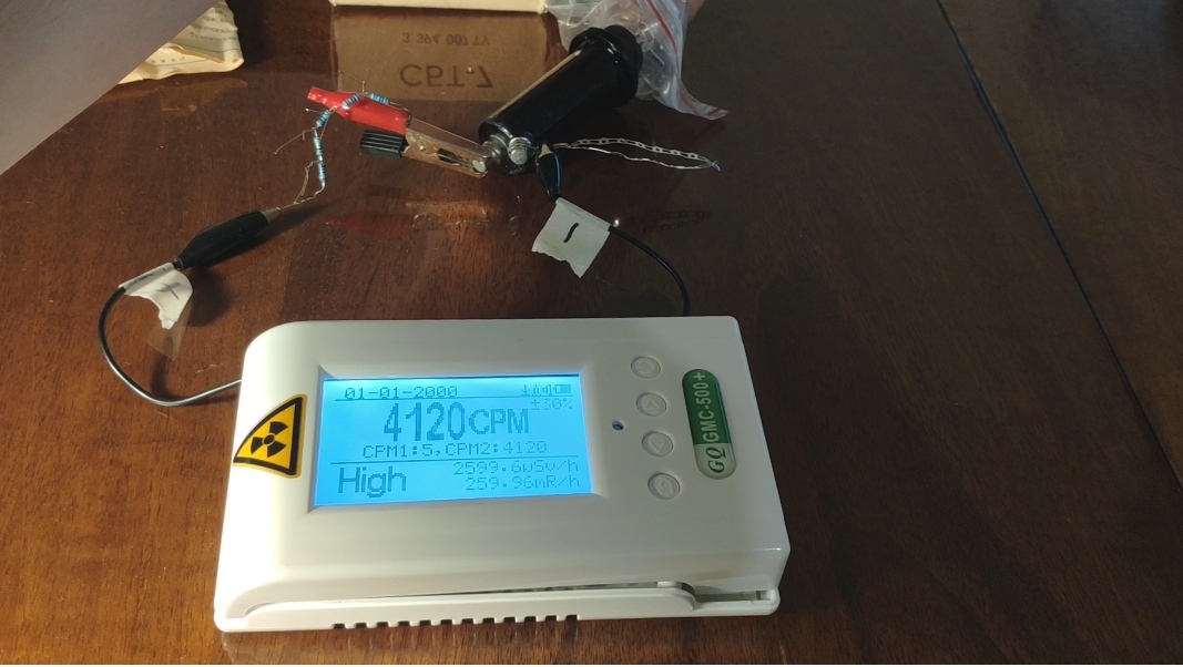 |
Edited by - nonus on 07/04/2024 00:06:37 |
 |
|
| Reply #41
nonus
  
38 Posts |
|
| |
 Topic Topic  |
|

