| Author |
 Topic Topic  |
|
|
atomic.dave
   
USA
65 Posts |
 Posted - 08/21/2011 : 12:46:42 Posted - 08/21/2011 : 12:46:42


|
Here are some notes from a Geigerbot user Osamu:
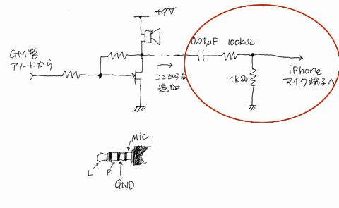
Schematic for using the headset input by Osamu. He notes:
"At first, I was trying to connect the output to mic input through
decoupling capacitor, but iPhone did not detect the signal. Then, I
happened to realize that I should have connect without the capacitor,
and it worked. The point is that you should connect iPhone's mic input
to the resistor without a decoupling capacitor.
It seems that iPhone detects DC load to switch input to external mic.
Otherwise, it would pick up hum noise just by being touched on the mic
terminal on the earphone jack.
---
The points of this schematic are:
- Divide the output voltage (in this case, about 9Vp-p) down to about 0.1V
- Do not decouple the output and iPhone mic input. Let the DC bias on iPhone mic input drop"
Image Insert:

10.13 KB |
|
| Reply #1
ZLM
    
1271 Posts |
 Posted - 08/21/2011 : 16:25:25 Posted - 08/21/2011 : 16:25:25


|
| I think you do not need to do any thing on the line in-put. The GMC-080 already has a internal capacitor and resistor. You can just connect the data output to your iPhone Mic. port. |
 |
|
| Reply #2
atomic.dave
   
USA
65 Posts |
 Posted - 08/28/2011 : 20:00:18 Posted - 08/28/2011 : 20:00:18


|
| As suggested by odiez, I took a 3 conductor 1/8 plug and spliced it to a 4 conductor, but made sure to cross the ground and signal wires over. (ground from iphone side to white on geiger side, and ground from geiger side to yellow (mic) on iphone side. This definitely is the best way to create a data cable for iphone/ipad as using only a 4 conductor on both sides had its problems such as disconnecting when the iphone slept or powered down. Or sometimes it would disconnect even going out of geigerbot even though it was running in the background. Added bonus is its easier to remember which plug goes where as the iphone takes the 4, and the geiger takes the 3... |
 |
|
| |
 Topic Topic  |
|
|
|

