| Author |
 Topic Topic  |
|
|
Paladin

7 Posts |
 Posted - 12/02/2019 : 16:21:19 Posted - 12/02/2019 : 16:21:19


|
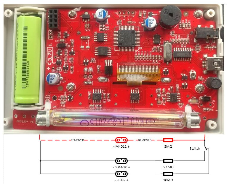
Before I make any purchases, I want to check to see if my understanding is correct and if this is feasible. I am only getting my questions halfway answered by reading other posts. My goal is to add two remote probes in a second enclosure that can switch between a SBM-20 and a SBT-9 (for alpha detection).
GMC-300E+ w/ "GMC320+ V6.1 2017.08.10" labeled board.
Image Insert:
107069 bytes
Is this feasible?
Are the resistors correct (bypass 3Mohm R15, 10Mohm for SBT-9, 5.1MOhm for SBM-20)?
Do I need to adjust voltages for each tube? Is this done with R14? Will this make switching between tubes without adjustments not feasible? |
|
| Reply #1
ullix

Germany
1247 Posts |
Posted - 12/03/2019 : 05:25:45
|
I have done something similar and with the same type GME300E+, so I am confident it will work.
One important aspect to keep in mind is that the anode resistors - in your drawing 5.1 and 10M - have to be placed as near as possible to the anode! Very important, or your signals get messed up. GeigerLog can do a test for Poisson conformity; if the signals are messed up, it will not conform. Check, once you have some records.
I can't comment on anode resistors. Take whatever the specs say (gut feeling says that 10M is high, but if its in the specs, use it).
Re the voltage it is also best to follow specs. Though there is some leeway to compromise. A test will tell.
Lastly, you don't necessarily need a switch. Actually, you could keep all 3 tubes active. Of course, background and signal would come from the sum of all tubes.
The only thing absolutely to consider is the count rate. Search here in the forum for a lengthy discussion of the impact that the limited power of the HighVoltage supply has. If the counts are too high, then the voltage will collapse, and count rate goes to zero. But it should only be a concern of countrate CPM= 10000 and higher. So this limit is reached sooner with 3 tubes combined, but for near background signals it would be ok.
Yes, R14 is the one to use for adjusting the voltage. When you measure voltage be aware that you need a 1 Gigaohm (or similar) resistor when measuring voltage with a DVM!
Let us know the results!
|
 |
|
| Reply #2
Paladin
7 Posts |
Posted - 12/03/2019 : 09:51:49
|
Thanks for the help! More questions:
-Resistor placed as near as possible to the tube (+), correct?
-I have done research, but specs aren't clear. Can someone please confirm:
--GMC-300E+ typically operates at 400v with a max of 500v?
--M4011 380-450v (400v recommended) w/ 3Mohm resistor (included as R15)?
--SBT-9 320-420v (380v recommended) w/ 10Mohm resistor?
--SBM-20 350v-475v (400v recommended) w/ 5.1Mohm resistor?
-Can I keep a single voltage setting and switch between tubes with the physical switch? (I�m not an electrician, so I may be misunderstanding how the resistors in series will affect tube voltage.)
-What wattage rating do I need for the series resistor and the 1Gohm multimeter probe resistor?
|
|
|
| Reply #3
Damien68
France
780 Posts |
Posted - 12/04/2019 : 01:25:13
|
@Paladin
The anode resistance will not change the voltage of the tube in its normal state (because when the tube does not detect a particle, its impedance is infinite).
When the tube receives a particle, it forms an electric arc inside the tube between the ande and the cathode, at this time we have a shortcut between the anode and the cathode of the tube, so the anode resistance is there to limit the shortcut current.
It is important that the anode resistance is as close as possible to the anode of the tube because the cable between the resistor and the anode constitutes itself a parasitic capacitance and parasitic inductance which increase a bit the pulsed discharge current during the shortcut. This has the effect of lengthening the blind time (pulse width), and also degrade the tube faster.
I thing you can keep 390v for SBT-9/SBM-20 usage
For the choice of the anode resistance, it is necessary to check the maximum voltage supported by the resistance because it will take pulses of 380 / 400v. standard resistors only support 200 / 300v. if we use a standard resistance, it will work but in the long run, there will be electromigration effects and it will cut itself.
the best is to choose a resistance specific to high voltages but is more expensive. we can also divide the resistance into 2 parts:
2 resistors of 5Mohms/300v in serie is equivalent to one of 10M 600v. but it's less good but it should work.
Your data about SBT-9 and SMB-20 are good, I don't know about the others.
but rather than the SBT-9 you could consider the LND-712 which seems to me better but requires 500v, even if GMC-300E+ can supply it he may consume much more. so SBT-9 may be the best choice.
there is no worries about the wattage of the resistance of 1G to probe, the dissiped power is: 400 * 400/1000000000 = 0.16mW
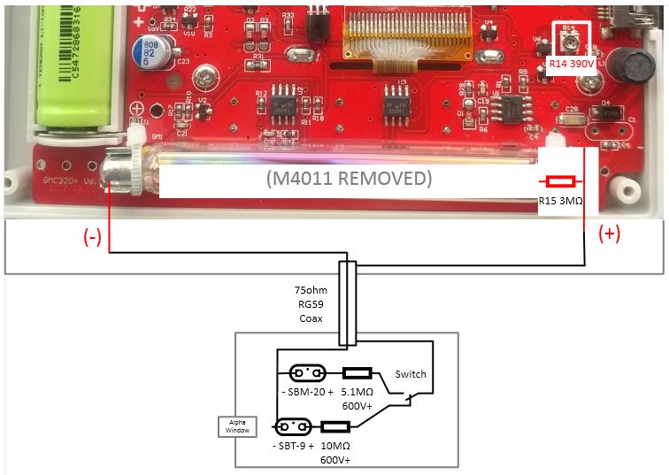
Your electrical scheme seems good, but you have to be careful because to detect pulses, the meter measures the current that passes through the cathode of the tube. it is therefore the cathode cable which constitutes the hot cable, it is necessary that there can't have any contact between him and other things, for example should not be able to touch it with the hands, otherwise it could cause EMI interferences. If you use coaxial cable, place the cathode on inside wire, and 'anode resistor pad' on shield wire.
|
Mastery is acquired by studying, with it everything becomes simple |
Edited by - Damien68 on 12/04/2019 02:19:44 |
|
|
| Reply #4
Paladin
7 Posts |
Posted - 12/04/2019 : 11:12:20
|
I was planning on using plain twin lead wire and it will of course be DC insulated by its jacket. Are you saying that is a bad idea? I need to shield the cathode wire (to (-) on board) from RF interference with coax? How necessary is this? Will something like plain 75ohm RG59 TV cable work?
Image Insert:
70519 bytes |
|
|
| Reply #5
Damien68
France
780 Posts |
Posted - 12/04/2019 : 12:10:39
|
you can try with a simple plain twin lead wire, it certainly work. coax is better and will exhibit less interference.
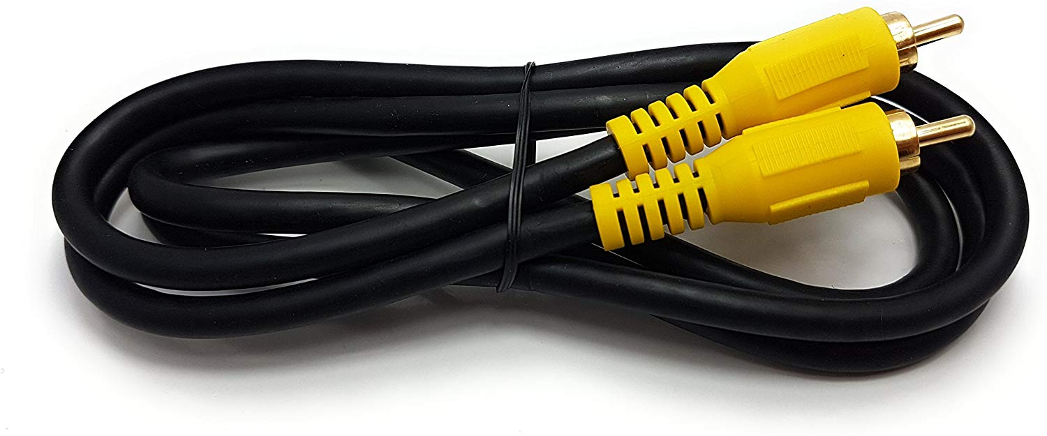
If you use a coaxial cable it's not necessary that it's big RG59 is ok but a simple flexible coaxial like RCA audio patchcord is adequate.
Image Insert:
87233 bytes
https://www.amazon.fr/Ragai-Digital-Coaxial-Composite-Disponible/dp/B077T11GVY/ref=asc_df_B077T11GVY/ |
Mastery is acquired by studying, with it everything becomes simple |
Edited by - Damien68 on 12/04/2019 12:23:46 |
|
|
| Reply #6
Paladin
7 Posts |
Posted - 12/04/2019 : 13:31:57
|
One more time, just to confirm: Cathode (-) should be center conductor on the coax and (+) should be shield (resistor between shield and (+) on tube)?
Any danger of arcing because of high voltage and close components in my design (like in the switch)?
RCA cable is a good idea. That way I can install jacks on the probe and meter. |
|
|
| Reply #7
Paladin
7 Posts |
Posted - 12/04/2019 : 13:45:11
|
| Why 470Kohm? (Just curious why that specific resistance.) The 470Kohm goes as close to the board as possible (before connecting to the coax)? Is this to prevent shorting of the coax shield to other parts of the device? Will this added resistance be enough to noticeably effect the tube readings? |
|
|
| Reply #8
Damien68
France
780 Posts |
Posted - 12/05/2019 : 01:31:48
|
Yes: Cathode (-) should be center conductor on the coax and (+) should be shield
Standard 230Vac switch is good, standard (air gap) isolation distance is 2.5mm for 400vdc, can be reduced if we place insulation material.
470k because with 500v output, this value limit the current to 1mA which in case of short circuit makes the current harmless for the card.
This in case of when the meter is connected by its USB cable, in this case it shares his ground with the ground of the host computer (by the usb cable). So what must be avoided is that there can be have a loopback between the 500v output and any point of the extented ground. But you can use 100k i think that it may be better and more than enough. I did not test it but I do not think it can reduce performance. afterwards the anode resistances can be reduced by the value of the inserted resistance.
yes the best is to place it as closing of PCB as possible to output the 400v signal.
But if you don't have connectors on the coaxiale extention and don't have shortcut risk, there is no need to insert resistor protection.
in any case it will be necessary to be careful to not touch any of the contacts, to protect the reader and his host. but with limiting resistance the risk is marginal or non-existent. |
Mastery is acquired by studying, with it everything becomes simple |
Edited by - Damien68 on 12/05/2019 06:01:07 |
|
|
| Reply #9
Redshiftzero

Sweden
11 Posts |
Posted - 12/10/2022 : 07:44:03
|
I'm bit confused what kind of resistor one can use for this?
I dont even find a shop in my country that sells a 10Mohm resistor that can handle 600v .
Found one that says working voltage 250V but that one does not do the trick for SBT-9 tube?
https://www.electrokit.com/en/product/resistor-carbon-film-0-25w-10mohm-10m/
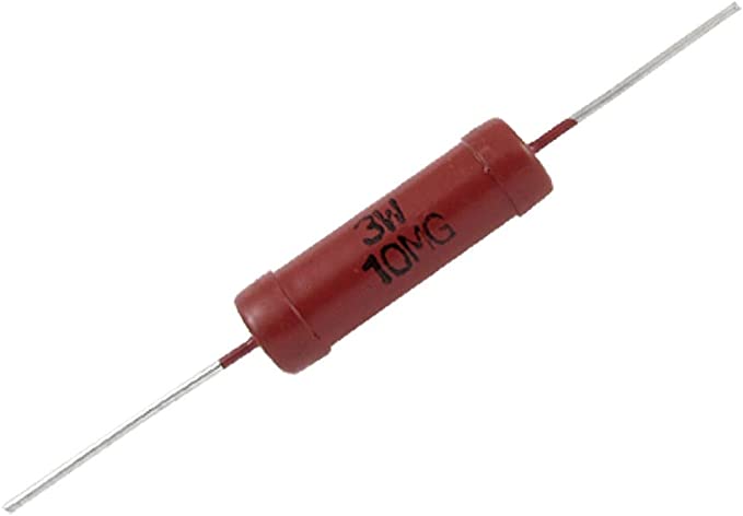
On Amazon there are some red resistors for high current applications but did not fins specs for voltage on them..
 |
*beep* *boop* |
|
|
| Reply #10
Redshiftzero
Sweden
11 Posts |
Posted - 12/10/2022 : 07:54:36
|
Or maybe this?
NIKKOHM RNP-140UHR010JZ03-1 High power resistor 10 m#8486; Radial lead TO-247 140 W 5 %
https://www.conrad.com/p/nikkohm-rnp-140uhr010jz03-1-high-power-resistor-10-m-radial-lead-to-247-140-w-5-1-pcs-1653485
Type Radial lead
Type TO-247
Resistance 10 m#8486;
Power rating 140 W
Tolerance � 5 %
Temperature coefficient 250 ppm
Length 20 mm
Width 16 mm
Height 4.8 mm
CS 10.16 mm
Max. temperature +175 �C
Min. temperature -55 �C
Threshold voltage 2500 V
Content 1 pc(s)
Dim (L x W x H) 20 x 16 x 4.8 mm
Type RNP-140UHR010JZ03
Product type High power resistor |
*beep* *boop* |
|
|
| Reply #11
Damien68
France
780 Posts |
Posted - 12/10/2022 : 13:28:39
|
the Conrad resistor is 10 milli-ohms not 10 Mega-ohms, so it can't work,
the red one should be suitable, it is a coiled resistor, there will be no dielectric breakdown problems or electro migration as there may be with the mini resistors.
|
Mastery is acquired by studying, with it everything becomes simple |
Edited by - Damien68 on 12/11/2022 00:10:46 |
|
|
| Reply #12
ullix
Germany
1247 Posts |
Posted - 12/11/2022 : 00:46:15
|
| What led you to the conclusion that you need a 10MOhm resistor, and not use the built-in 4 (5?)MOhm one? |
|
|
| Reply #13
Damien68
France
780 Posts |
Posted - 12/11/2022 : 02:33:26
|
if you house the tube or tubes in the meter, you can keep the resistance already present on the printed circuit, if you deport the tubes in an external probe connected by a cable, it is better to take the 400v before the internal resistance and add one in the external probe.
in principle, the resistor must be as close as possible to the anode of the tube for the following reasons:
normally there is 400v between the anode and the cathode of the tube. when radiation passes through the tube, there is an ionization and an electric arc between the anode and the cathode inside the tube, this is like a shortcut, the voltage between the anode and the cathode then goes from 400v to 0v.
the energy then dissipated during this electric arc is then Q=CU:
C= capacity between the anode and the cathode.
U= voltage variation between the anode and the cathode =400v.
the intrinsic capacitance of the tube is a few pico farads (pF). if, for example, a 1m cable is added without adding resistance on the side of the tube, this will greatly increase the capacitance seen by the tube, which will have the effect of greatly increasing the energy dissipated by each of the electric arcs in the tube and will greatly reduce the life time of the tube and greatly increase the dead time. but that won't stop it from working. |
Mastery is acquired by studying, with it everything becomes simple |
Edited by - Damien68 on 12/11/2022 02:39:44 |
|
|
| Reply #14
Redshiftzero
Sweden
11 Posts |
Posted - 12/11/2022 : 05:44:55
|
quote:
Originally posted by Damien68
if you house the tube or tubes in the meter, you can keep the resistance already present on the printed circuit, if you deport the tubes in an external probe connected by a cable, it is better to take the 400v before the internal resistance and add one in the external probe.
in principle, the resistor must be as close as possible to the anode of the tube for the following reasons:
normally there is 400v between the anode and the cathode of the tube. when radiation passes through the tube, there is an ionization and an electric arc between the anode and the cathode inside the tube, this is like a shortcut, the voltage between the anode and the cathode then goes from 400v to 0v.
the energy then dissipated during this electric arc is then Q=CU:
C= capacity between the anode and the cathode.
U= voltage variation between the anode and the cathode =400v.
the intrinsic capacitance of the tube is a few pico farads (pF). if, for example, a 1m cable is added without adding resistance on the side of the tube, this will greatly increase the capacitance seen by the tube, which will have the effect of greatly increasing the energy dissipated by each of the electric arcs in the tube and will greatly reduce the life time of the tube and greatly increase the dead time. but that won't stop it from working.
Thank you for the explanation!
That is great news if I do not need to add an extra resistor for the SBT-9.
I'm not sure exactly how I will place it yet but if possible i'll try to house it next to the original one and not as a external probe.
|
*beep* *boop* |
Edited by - Redshiftzero on 12/11/2022 05:56:00 |
|
|
| Reply #15
Redshiftzero
Sweden
11 Posts |
Posted - 12/11/2022 : 05:53:14
|
quote:
Originally posted by ullix
What led you to the conclusion that you need a 10MOhm resistor, and not use the built-in 4 (5?)MOhm one?
This is what I understood from reading the info I could find about pairing the GMC300e with the SBT-9.
But it seems that I had misunderstood this as Damien68 explained in his post above.
|
*beep* *boop* |
|
|
| Reply #16
ullix
Germany
1247 Posts |
|
| |
Topic |
|