| T O P I C R E V I E W |
| mojo66 |
Posted - 11/25/2022 : 10:08:45
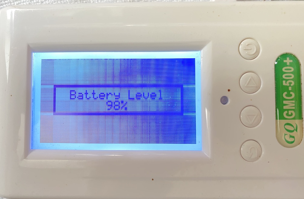
I have accidentally put the battery in reverse on my GMC 500+ and now the device is stuck at "Battery Level":

I have beeped all diodes and they are fine. What can I do to fix this problem? |
| 31 L A T E S T R E P L I E S (Newest First) |
| Damien68 |
Posted - 01/26/2023 : 08:43:11
quote:
Originally posted by mojo66
I didn't know that the counter needs a battery in order to work correctly.
yes it is not necessarily very natural, it should be written in a manual. |
| mojo66 |
Posted - 01/26/2023 : 05:53:20
quote:
Originally posted by Damien68
Hi mojo66,
during your tests, are you sure that there was a battery placed in the counter?
in fact, the counter needs its battery to operate without worries.
Thank you. I didn't know that the counter needs a battery in order to work correctly. That explains a lot because all the measurements were taken with the battery out. |
| Damien68 |
Posted - 01/26/2023 : 01:55:47
Hi mojo66,
during your tests, are you sure that there was a battery placed in the counter? and that battery is not dead?
I have already observed this kind of behavior on my counter if I power it only by USB and without placing a battery inside.
in fact, the counter needs its battery to operate without worries.
without its battery it may or may not work depending of what it's plugged into.
if you plug it (without battery) on a PC that respects stricly the USB specifications it should not work as it should because on USB specifacation, there are mendatory reaction speed limitations of regulation of the provided 5v which pose a problem. but with a battery it works without worries. let's say that the battery also acts as a capacitor.
|
| mojo66 |
Posted - 01/25/2023 : 20:51:22
quote:
Originally posted by EmfDev
R36 is 1.5kOhms
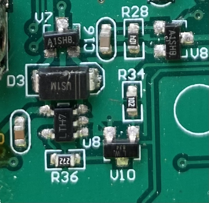
I shot this image before I started working on the PCB. R36 is clearly marked "272"!

Also I don't think the difference between 152, 272 and 332 should matter much in this case, definitely not result in noise and flicker. I think something else is still wrong. Wouldn't be surprised if the replacement parts I got from eBay are to blame. |
| EmfDev |
Posted - 01/25/2023 : 14:39:42
You can try to put 2 in parallel stacked together to lower resistance. |
| EmfDev |
Posted - 01/25/2023 : 14:32:01
R36 is 1.5kOhms and without it, the battery will not charge. The backlight and speaker directly get power from battery. If battery is low, theyre going to be affected. You can try to use the 3k3 and wait for few minutes/hours to charge the battery. It may stop the flickering. It will take longer to charge the battery. |
| mojo66 |
Posted - 01/25/2023 : 10:58:54
Thank you Damien68, the original R36 is gone for good. I tried to replace it with a 3k3 which is the closest I could find in my fundus and a bodge wire to U8 but this resulted in a weird crackling noise from the speaker and display flicker. That's why I left it unpopulated for now. |
| Damien68 |
Posted - 01/25/2023 : 07:50:58
Hi mojo66,
R36 is used by U8 to set the battery recharge current. if R36 is missing it is normal that the battery does not recharge. if you still have the resistor, you can reassemble it and replace the missing pad with a very thin copper wire without insulation connected between the missing pad and the pad 5 of U8. if you no longer have the resistor, you can replace it with a 2k7/0603 resistor (0603 is the package type), or replace it with a traditional 2k7 resistor with pins (smallest possible resistor 1/16W or smaller) and connect one pin to pad 5 of U8 and the other pin to pad 3 of V10 (follow the traces on the PCB)
you can also leave everything as it is, it won't recharge the battery but it's safe. |
| mojo66 |
Posted - 01/25/2023 : 05:29:44
Good news, I fixed it by long-pressing the power button!
In battery-only mode the device is now working normally again.
With the battery inserted, when I connect USB it does acknowledge by displaying the USB icon, but it doesn't seem to charge the battery.
The probable reason is that during all the micro-soldering, I accidentally ripped R36 off the PCB including one of its soldering pads (the one in the opposite direction of V10), so right now R36 is missing. |
| EmfDev |
Posted - 01/18/2023 : 11:29:40
Try to remove the USB, keep the battery in #1 state. Then please check the V7 V8 and others in reply #18 |
| mojo66 |
Posted - 01/17/2023 : 19:45:58
Well you say the voltages I measured at U6 are correct but the device still is in the state depicted at posting #1, which means something else must not be working correctly. Could it be the CPU? |
| EmfDev |
Posted - 01/17/2023 : 15:29:29
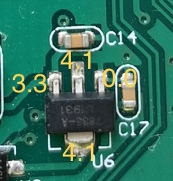
What do you mean by dead? It seems the voltage around the transistor are correct. 4.1V is input from battery the middle pin of 3 pins. |
| mojo66 |
Posted - 01/17/2023 : 00:27:07
quote:
Originally posted by EmfDev
Directly inject the 4.2V to U6 input pin will skip all power switch part.
Thank you.
U6 reads "7883-A U1931" I couldn't find a matching transistor, so I don't know what you mean with "input pin"
I measured the following voltages on U6 while connected to USB power:

Does this mean the CPU is dead? |
| EmfDev |
Posted - 01/09/2023 : 13:06:04
From our hardware engineer:
I assume the problem is that the unit can not be off without USB cable and stay on battery level screen.
The battery positive current through V7 and V8 transistors to U6 for the 3.3V CPU power.
In battery only mode, to get 3.3V working voltage, both V7 and V8 gate pins need to be low. In power off mode, the V8 gate pin is high. If this pin is low after power off, then the screen will show battery level.
In USB connected mode, V7 gate pin is high and V8 gate pin is low(<1V). In this case, the V8 gate pin is pulled low by V9 transistor collector pin via 10K R30. The V9 base pin connected to USB power via 10K R37.
Directly inject the 4.2V to U6 input pin will skip all power switch part.
|
| mojo66 |
Posted - 01/09/2023 : 07:29:31
@EmfDev : Thank you for your help. That is correct, after replacing U8 the symptoms are the same. I'd like to verify that the CPU is intact. U8 and the other MOSFETs are just latches that provide the rest of the device with either battery or USB power and handle battery charging. Can you ask the hardware engineer at which point on the PCB, with the battery disconnected, I can safely inject 5V to verify that the CPU is OK? |
| EmfDev |
Posted - 01/06/2023 : 12:29:50
Hi mojo66, I asked our hardware engineer, he said you just need to change the u8. V10 should be ok. V10 is 2n3904 part number. After replacing the u8, does your device still not work? |
| mojo66 |
Posted - 01/05/2023 : 03:07:04
@EmfDev : thank you for your help. I have used the forum e-mail feature, i.e. clicked on your nickname then "Click to send an E-Mail", perhaps the address is outdated, or it was treated as SPAM? The sender address was gq@mojo66.de
Anyway I have sent an e-mail to support asking for further advice. Thank you. |
| EmfDev |
Posted - 01/04/2023 : 10:54:57
Hi mojo66, asked support and said they can send you the part number but we need to confirm the correct part. And it seemed I did not receive your email. I will send you one and if you do not receive it please email support@gqelectronicsllc.com |
| mojo66 |
Posted - 01/04/2023 : 05:32:49
I have replaced U8 without any change. The only part I haven't replaced is V10 because I can't find "LW 834". It doesn't have a short, so I assume it is ok.
I'm out of ideas now and have sent you an email. Thanks. |
| EmfDev |
Posted - 01/03/2023 : 12:55:33
Hi mojo66, if you need some of the small parts, let us know we may be able to send you. But you may need to pay for shipping. (I need to verify with support). But of course you can also get them locally if it is faster or cheaper. |
| mojo66 |
Posted - 01/01/2023 : 03:08:31
I have replaced V7, and all MOSFET and diodes check out now. The only IC in the power management section that I can't check is the LTH7 Li-Ion charging controller (U8). Once the new part arrives I will update this post.
I have also verified that LTH7 is indeed configured in reverse polarity protection and thus have removed my snarky comment. Apologies. |
| EmfDev |
Posted - 12/28/2022 : 10:36:57
Our engineer has said they have added a diode for protection when battery is reversed. But if you plug it in to USB/charge, it will still cause problems. |
| Damien68 |
Posted - 12/28/2022 : 06:19:38
if you short the P-MOS and if there is a battery and a 5v USB power supply in same time, the 5V USB will go directly into the battery and there is a real risk of the battery exploding, it's even more than a risk and the battery will really blow up.
On P-MOS Vgs is a negative voltage, and if |Vgs| > |Vgsth| (Vgs threshold) the transistor acte like a short (a low value resistor in fact). and current can flows in both directions. otherwise if the transistor is not biased it acte like a diode (so-called parasitic diode) and the current can flow from drain to source (because is a P-MOS).
PS In the case of an N-MOS transistor everything is reversed. |
| mojo66 |
Posted - 12/28/2022 : 04:19:21
V7 is a P-MOSFET. In-circuit it measured a short in both directions between source and drain so I de-soldered it. Out of circuit it measured 0.55/1.9V.
It didn't change anything though In the end the MOSFETs are just latches, correct? Shouldn't I be able to bridge a connection so I can at least use the device with either the battery or the USB?
@EmfDev what do I have to do to receive the replacement parts? |
| Damien68 |
Posted - 12/26/2022 : 03:04:49
Hi Bobakman, these are great articles,
The principle of operation of these diagrams are very similar to old 'Samsung' phone designs where in fact it is always the battery that supplies the load and the external power supply comes to recharge the battery when it discharges.
in GMC counters when it is powered by an external power supply, the battery is totally isolated and the device is powered directly by the 5 volts coming from the USB. which avoids having permanent charge-discharge cycles of the battery and therefore it avoids using the batteries unnecessarily.
PS: in the case of old telephones they worked like this for reasons of electrical voltage regulations because of very fast and very violent transient due to the operation of GSM (2G), also by connecting directly to the battery, this allowed to to have a roughly stable voltage.
In GMC counters, there is a P-MOS mounted in 'ideal diode' or 'O-Ring' as on your articles, but I believe that the charge controller is connected before (on the unprotected area). Maybe he was the one who burned down. or not ... :=) |
| Bobakman |
Posted - 12/25/2022 : 15:10:44
As Damien68 Stated if the onboard charging is to be maintained the solutions are more complex. If one desires not to utilize the onboard charger and simply remove the battery for charging a PITA
then the Schottky appears to be a good choice. See links below for some insight.
https://www.edn.com/reverse-voltage-protection-for-battery-chargers/
https://www.edn.com/protecting-against-reverse-polarity-methods-examined-part-1/ |
| mojo66 |
Posted - 12/25/2022 : 02:12:12
@Damien68: https://en.wikipedia.org/wiki/Schottky_diode |
| Damien68 |
Posted - 12/23/2022 : 01:31:04
@mojo66:
a simple diode cannot work for 2 reasons:
- the first is that it loses between 0.5 and 0.8v which is too much for a battery voltage ranging from 4v2 to 2v8-3v.
- the second reason is that when you charge the battery the current needs to flow backwards so...
There are solutions but more complex. |
| Bobakman |
Posted - 12/22/2022 : 19:39:26
+1 for a reverse polarity protection circuit upgrade. Operator error is inevitable and the proper diode in the input power supply circuit is a great defense.
Bob |
| EmfDev |
Posted - 11/29/2022 : 16:31:19
Hi mojo66, unfortunately a transistor may have been damaged. You may need to send it back to us for repair or if you can solder, we may send you parts (this one I will need to check with support). |
| ullix |
Posted - 11/28/2022 : 01:33:38
Bummer <;-))
You did all the usual things, like taking the battery out, then shortening the battery contacts in the counter, waiting for a looooong time, then reinserting the battery?
That's all I can contribute. I guess Amazon will welcome you ...
|

