Probe Modifications
Printed from: GQ Electronics Technical Support Forum
Topic URL: http://www.gqelectronicsllc.com/forum/topic.asp?TOPIC_ID=3403
Printed on: 03/29/2026
Topic:
Topic author: Odiez1
Subject: Probe Modifications I want to extend the probe outside of the GMC-080 box. I drilled a hole and mounted a BNC connector, then wired the + and - of the tube to the BNC connection. It seems to work alight, but occasionally the LED will light up solid and it will kind of "scream" instead of click. Connecting the data port to a computer helps, and I've found that touching the screwdriver wile in the voltage adjustment pot will stop the squealing also. It seems that the coax wire has an effect of the circuit functioning. The longer the coax length the worse it seems to work.
Replies:
Posted on: 08/05/2011 14:37:48
Message:
Are there any tips you can give me to aid in reliably extending the GM tube?
Image Insert: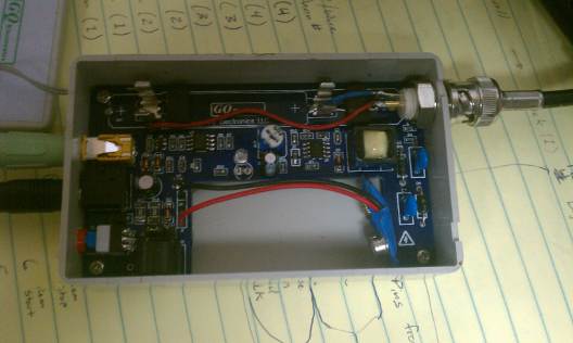
25.91 KB
Thanks Very Much!
Reply author: Odiez1
Replied on: 08/07/2011 20:10:33
Message:
Could it have something to do with the 50ohm impedance? There is no impedance in the circuit board alone, and maybe it's causing a kind of feedback.. I'll try a pair of single wires setup extension and report back.
Reply author: ZLM
Replied on: 08/08/2011 11:21:14
Message:
That looks good.
I believe that is noise interference.
There is a capacitor C2 on board. Try to parallel a 0.1uF capacitor on C2.
But increase that C2 too much may affect the count reading on higher counting.
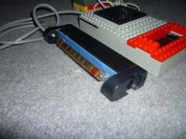
Can you post your complete set after that? I just want to see what is your external probe looks like.
Reply author: Odiez1
Replied on: 08/10/2011 17:32:14
Message:
Awesome! Thanks for the info. I'll be trying that tonight hopefully, tomorrow defiantly.
There are more pictures to come. :)
My goal is to have a remotely mounted probe outside a building (the GMC-080 inside) on the foothills of Sacramento, so I can log into the computer remotely to get readings.
This is a fantastic device, especially for the price point.
Previously I bought a Chaney kit GM counter (which I killed by connecting a power supply in reverse) but your product is far superior and complete. The Chaney kit is only a circuit board and components, and twice the price!
Kudos to GQ!
Image Insert: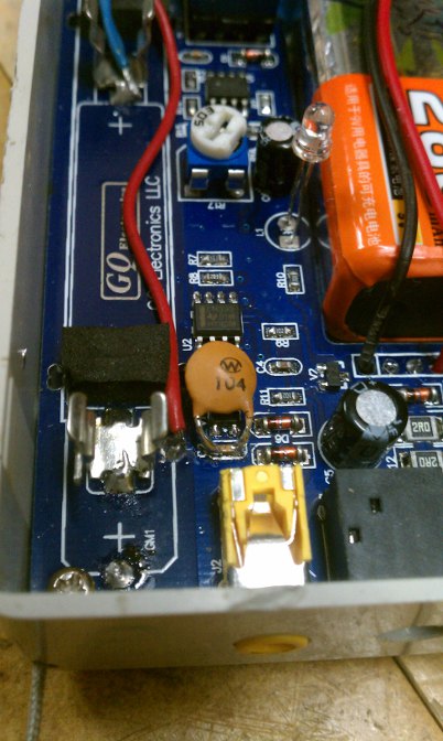
76.65 KB
Image Insert: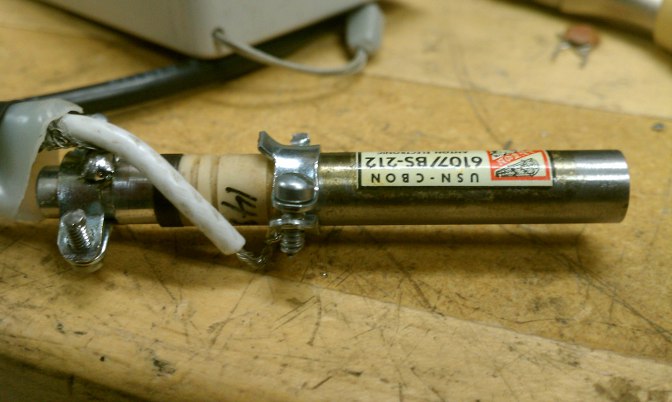
57.57 KB
Reply author: atomic.dave
Replied on: 08/11/2011 17:55:20
Message:
I just go the GQ 080 today, and I must say it is a well put together kit. I installed the SI-29BG tube and am waiting for the battery to charge before I take it for a drive... Gonna hook it up to my iphone and geigerbot.
quote:
Originally posted by atomic.dave
I also have bought a chaney kit, but got the one with the digital display. It doesn't work very well with the battery as it sucks the power in a day, but when you power it up with a ac adapter, it works pretty darn well.
My second kit is from brohogan. An awesome Arduino based geiger. It has a LCD, USB power, and data transfer to arduino.
I just ordered the GQ 080 and am awaiting delivery. Can't wait to play with it. But haven't decided which tube to use. I have three: SBM-20, SI-29BG and LND-712. I think I'll use the SI-29BG as the size will be perfect for the small enclosure. I would use the LND, but it mostly senses Alpha, and requires a window for the mica front.
I have also tried doing remote probes with little success, as I kept getting elevated counts, and grounding issues. The first probe was with a flashlight case for a LND-712, the second one was with two tubes- SBM and LND in front. But kept having grounding problems. Now, I just bought a empty probe from an old CDV-700, that I am gonna try that already has the wire. I'll try putting the LND or the SI-29BG in it.quote:
Originally posted by Odiez1
Awesome! Thanks for the info. I'll be trying that tonight hopefully, tomorrow defiantly.
There are more pictures to come. :)
My goal is to have a remotely mounted probe outside a building (the GMC-080 inside) on the foothills of Sacramento, so I can log into the computer remotely to get readings.
This is a fantastic device, especially for the price point.
Previously I bought a Chaney kit GM counter (which I killed by connecting a power supply in reverse) but your product is far superior and complete. The Chaney kit is only a circuit board and components, and twice the price!
Kudos to GQ!
Image Insert:
120.41�KB
Reply author: Odiez1
Replied on: 08/11/2011 20:57:54
Message:
Hey there ZLM.
The extra cap works great. At first I thought it was dead, but it was just the battery. Fresh juice and it was going nuts on my cdv-700 check source.
Thanks for the tip! :)
Now, lets all look for the little bits of Fukushima Daiichi floating around.
Www.enenews.com
I check it every day.
Reply author: ZLM
Replied on: 08/11/2011 22:13:53
Message:
thanks for sharing all your work.
Reply author: Odiez1
Replied on: 08/12/2011 10:19:12
Message:
quote:
Originally posted by atomic.dave
I have also tried doing remote probes with little success, as I kept getting elevated counts, and grounding issues. The first probe was with a flashlight case for a LND-712, the second one was with two tubes- SBM and LND in front. But kept having grounding problems. Now, I just bought a empty probe from an old CDV-700, that I am gonna try that already has the wire. I'll try putting the LND or the SI-29BG in it.
I refurbished my CDV-700 probe by adding a BNC connector. The original wire sheathing was pulling out of the probe end. After I got into it, I found the tube socket was glued into the bottom of the handle with a lot of white solid glue. You have to pry the socket out by twisting it with some pliers or whatever.
I broke the socket in the process. Then I carefully drilled out the glue with a 1/2" drill bit, and polished off the rest with a Dremel tool. I found the tube socket on ebay and bought 20 of them (way too many as I only needed 1).
If you need a replacement socket reply here and we can work it out if you want.
I guess for a different tube you won't need the original socket...
Reply author: ENIGMA6
Replied on: 08/14/2011 14:59:47
Message:
Check your negative and positive connections carefully on BOTH sides of the board. Unless I am badly mistaken, it appears that you have connected the negative connection on the board to the center of the BNC connector, and the positive connection on the board to the outside or shield of the BNC connector. This is exactly reverse of what it should be. You will also need to connect the center of the coax to the end of the geiger tube. The shield should be connected to the longer part of the tube. I accidently hooked up one backwards once. Didn't hurt anything but it was no where as sensative as when connected properly. If you reverse these so the shield is connected to the negative on the board [where the red wire is now] it will probably stop the feedback.
Reply author: ENIGMA6
Replied on: 08/14/2011 15:02:29
Message:
To simplify, hook the red wire to the outside of of the BNC connector, and the blue wire to the center connector, then reverse the connections at the tube.
Reply author: Odiez1
Replied on: 08/16/2011 09:52:32
Message:
quote:
Originally posted by ENIGMA6
To simplify, hook the red wire to the outside of of the BNC connector, and the blue wire to the center connector, then reverse the connections at the tube.
I Hear you, and originally I hooked it up that way. But I found that having the - Neg term on the shield of the coax caused more false clicks when I touched the connectors than when the + Pos was on the shield. I guess my capacitance causes less interference when touching the + than it does to the -.
Probably related to the way the flyback transformer "sees" the variation in the steady voltage when the neutron pops off the center wire of the tube.
But ZLM can probably give more insight here.
Once I got that .1uF cap in there all the problems cleared up. The click sound seems to be stronger/ louder also, but I believe the battery life has lessened some. I use the wall wort mostly anyway.
Reply author: ENIGMA6
Replied on: 08/17/2011 12:03:28
Message:
OK, what ever works best for you. I haven't attempted an extension probe for mine yet. Did you notice the positive connection at the end of the board is immediately adjacent to the location of the negative clip? When I first received mine I thought that the clip location wasw the positive connection but found out differently after close exam of both sides of the board.
Reply author: Odiez1
Replied on: 08/17/2011 15:19:12
Message:
Yeah. I guess the designer wanted a ton of flexibility in the types of tubes mounted in there. There are 3 + connections on mine, 2 sets for the included clips on one side, the opposite has 1 for a single wire. There are 2 - connections, 1 set for the clip and 1 for a wire, right next to each other (where my red wire is going). I figured I'd make the wires as short as possible to the connector...
BTW, check out the new topic with schematic for the 6107 tube. I think it explains why my wiring is reversed.. The - is connected to the pulse acquisition circuits directly. The + side is 'floating' on the HV side all by itself.
Reply author: fearlessjohn
Replied on: 01/05/2012 02:38:17
Message:
Hi gentlemen, coax cable used to remote a sensor adds a lot of capacity to ground. RG58 for example has minimum 100 pF/m. Ludlum and Eberline position anode resistors (they use 3.2 MOhms) as close as possible to the GM pancake anode,i.e. right in the pancake tube "lollypop" casing. This minimizes influence of capacity that affects adversely the transmission of pulses to the counter board. Hope this will help you.
Reply author: Odiez1
Replied on: 01/23/2012 17:44:17
Message:
That explains why the added capacitance on C2 canceled out the addition of the RG58. Fantastic info! Thank you.
GQ Electronics Technical Support Forum : http://www.gqelectronicsllc.com/forum/
© Copyright since 2011