| Author |
 Topic Topic  |
|
|
blargg

USA
11 Posts |
 Posted - 04/01/2020 : 04:22:14 Posted - 04/01/2020 : 04:22:14


|
I just got a GMC-600+ a few days ago and the green LED was flashing for each click, but today I notice it's not flashing. It still flashes red once CPM exceeds medium threshold. I tried factory reset but no difference.
Is there some configuration flag that might be set to disable it? Thanks. |
Edited by - blargg on 04/08/2020 04:10:38
|
|
| Reply #1
EmfDev

2395 Posts |
Posted - 04/01/2020 : 08:44:14
|
| Hi blargg, that is unfortunate, do you want to completely disable the LED feature? You can turn it off under User Options. |
 |
|
| Reply #2
blargg
USA
11 Posts |
Posted - 04/01/2020 : 12:15:08
|
| No, I'd like the green LED to flash again when it detects radiation, like it did when I first got it. Could there be some bit/byte in the 256 configuration bytes that affects this? |
|
|
| Reply #3
EmfDev
2395 Posts |
Posted - 04/01/2020 : 12:50:24
|
| If the red led is working but the green does not work. It can mean that the LED is damaged. You can contact customer support for the warranty and your order number. |
|
|
| Reply #4
blargg
USA
11 Posts |
Posted - 04/01/2020 : 20:29:06
|
| I found that pressing slightly on the front panel near the LED makes the green flash work (red always works). I'm not keen on doing a whole warranty exchange process (do you pay shipping both ways?). I do electronics and have a grounded soldering iron (Hakko) and could try reflowing the LED pins in case it's just a cold solder joint. Given that the red works it seems like the fault must be at the LED. Let me know if I can try this without voiding the warranty. Thanks. |
|
|
| Reply #5
Damien68

France
780 Posts |
Posted - 04/01/2020 : 23:54:23
|
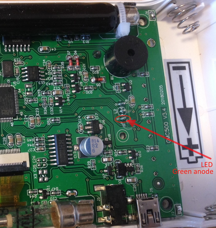
I do not know if we can open the device without losing the warranty, but you must be right, it must miss a solder (or cold one).
The LED must be a through-hole one as for the GMC-500 so the soldering does not require any advanced technicality but basic one anyway.
below I found the photo of a printed circuit model 500 the 600 must be very similar.
If you open the device, be careful not to bend the wires of the sensor which is fixed in the cover, so open the device to the minimum, but I don't know if it's allowed.
Image Insert:
375054 bytes |
Mastery is acquired by studying, with it everything becomes simple |
Edited by - Damien68 on 04/02/2020 00:12:28 |
|
|
| Reply #6
EmfDev
2395 Posts |
Posted - 04/02/2020 : 10:02:44
|
| Hi blargg I asked support and they said you can try to open the case without voiding the. And as Damien 68 posted, the PCB of 500 and 600 series are similar and the LED's resistor is R20. Also if the LED is broken (not fixable) we can send you a new one. And if you decide to do the warranty exchange/repair, we cover the shipping cost if it is bought under 30 days. |
|
|
| Reply #7
blargg
USA
11 Posts |
Posted - 04/03/2020 : 00:35:27
|
The LED seems to be bad. The circuit seems to be that the ARM puts 3.2V on either the G or R leads, depending on whether the current CPM is below or above the Medium threshold. Then the cathode (center pin of LED) is pulsed low through R20 via the LM339 comparator's open-collector output. I was measuring 3.2V on the G lead as expected, but the cathode of the LED would sometimes be 0V when the LED was malfunctioning, or 1.4V or so, with pulses to 0V on clicks and the LED properly flashing (using oscilloscope to check this). Putting pressure near R23 (near the USB) would affect operation. My best guess is that internal to the LED one of the leads was coming loose. Reflowing the leads didn't help, so I desoldered the LED but can't even get diode check on a multimeter to verify either red or green elements (diode check works fine on red and green LEDs I have). I plugged in a green LED on the PCB and it flashes fine. I had the board in a few positions with different pressure on it and that didn't seem to affect proper operation, so the pressure on the board before was probably shifting the bad LED's leads just right to affect the internal connection.
tl; dr: LED seems bad. Displayed symptoms of one lead coming loose internally and becoming open circuit. PM sent. |
Edited by - blargg on 04/03/2020 00:44:53 |
|
|
| Reply #8
Damien68
France
780 Posts |
Posted - 04/03/2020 : 08:02:45
|
the voltage between terminal of a lit red led is 1v6, for a green led is a little higher (between 2v and 2.2v), which explains why it is not necessarily testable with a diode tester rather made to test diodes between 0.3v and 1v2.
if the led is desoldered and only if it, you can test it with a 5v power supply and a 2K ohms resistor in series.
If you probe led green andode and led cathode with dual trace/probe oscilloscope, if you have 3v2 on the LED anode and in same time 0v on the cathode, the led is malfunction because it can't have more than 2v2 between anode and cathode. normaly cathode voltage can't drop below (about) 1v .. 1v2 when Led function is activated |
Mastery is acquired by studying, with it everything becomes simple |
Edited by - Damien68 on 04/03/2020 22:04:18 |
|
|
| Reply #9
blargg
USA
11 Posts |
Posted - 04/07/2020 : 19:24:21
|
New replacement LED arrived (with a spare). Diode test on meter lights both of red and green. Soldered one in and it's back to working correctly. I did manage to rip the red side's pad off the board when inserting the LED so had to solder a small jumper to the trace (scraped off the green conformal coating and tinned the trace beforehand).
While it was open I took a picture of the whole board, in case it's of any use. The clips on the sides are interesting because they are rotated 90 degrees from what they are on other models, where they hold one or two tubes vertically.
I'm enjoying this and my EMF-390 V2 that I purchased. The software is great on these, and I really like how involved GQ is with its users here. I've been logging some feedback to give about my experiences with these. I think I made the right choice with one of these over the Gamma Scout.


|
Edited by - blargg on 04/07/2020 19:31:53 |
|
|
| Reply #10
Damien68
France
780 Posts |
Posted - 04/07/2020 : 21:02:18
|
| good work |
Mastery is acquired by studying, with it everything becomes simple |
|
|
| Reply #11
EmfDev
2395 Posts |
Posted - 04/08/2020 : 09:07:42
|
| That's great! The clips act as a stopper so the case doesn't get pushed inside. :D |
|
|
| |
Topic |
|