| Author |
 Topic Topic  |
| Reply #1
ullix

Germany
1244 Posts |
 Posted - 11/04/2018 : 05:11:55 Posted - 11/04/2018 : 05:11:55


|
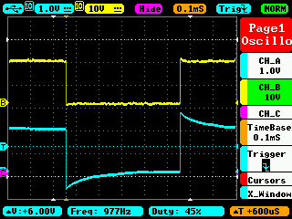
Before you get overly excited about my little scope, some warning on its limitation. The bandwidth is plenty good for all Geiger work, that is of no concern.
The input impedance, however, is only 1MOhm, and the voltage limit is +/- 40V only! Don't touch the HV with it!
But you need probes anyway (only one 1x probe is included) and with 2 probes like this https://www.amazon.de/gp/product/B01N8TFP8T/ref=od_aui_detailpages00?ie=UTF8&psc=1 you get 10MOhm input impedance (i.e. an impedance like your DVM has) and a 600V pp limit. So, you can touch your anode with the probe.
The disadvantage is that the probes cannot be compensated, neither at the probe nor at the scope. Using the built-in signal generator (also very helpful, with the much better Hantek scope you still get no signal generator!) and the 2 probes connected to it in 1x and 10x mode, you see the signal's distortion in 10x mode - but not in 1x mode - in the picture. (The yellow trace is 1x mode, I forgot to change the setting in the scope; it is not auto-detected).
Image Insert:
38912 bytes
Not nice, but one can live with it; just keep this in mind when you interpret your signals!
|
 |
|
| Reply #2
Stargazer 40
USA
431 Posts |
Posted - 11/04/2018 : 05:13:58
|
quote:
Originally posted by EmfDev
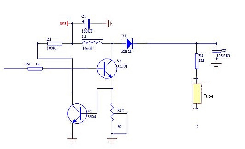
Tube 1, is from ground and the collector of transistor V3. And ground to collector of transistor V4 for tube 2.
Are V3 and V4 in same circuit location as V5 in this picture you posted to ullix's 500+ review thread?
Image Insert:
39063 bytes |
Stargazer 40 |
|
|
| Reply #3
Stargazer 40
USA
431 Posts |
Posted - 11/04/2018 : 05:21:42
|
quote:
Originally posted by ullix
Before you get overly excited about my little scope, some warning on its limitation. The bandwidth is plenty good for all Geiger work, that is of no concern.
The input impedance, however, is only 1MOhm, and the voltage limit is +/- 40V only! Don't touch the HV with it!
Not nice, but one can live with it; just keep this in mind when you interpret your signals!
Thanks ullix, the limitations are clearly presented in the US version as well. The compensation thing is also understood. I would use existing BNC 1-10X probes and add BNC to MCX converters to plug into scope. At this point I am still trying to understand GQ's choice of test points in the power supply circuit as their displays seem to eliminate the ambiguity of the dead time measure. |
Stargazer 40 |
|
|
| Reply #4
EmfDev

2415 Posts |
Posted - 11/05/2018 : 17:25:03
|
@Stargazer_40, that seems to be from the old version of hardware. I'll have to check the new schematic,
will update later. |
|
|
| Reply #5
ikerrg
United Kingdom
334 Posts |
Posted - 11/06/2018 : 10:57:35
|
| @EmfDev: Do you know anything new about the firmware update that includes the deadtime correction? From my point of view, you do not need to add any voltage correction for now (it is better to do the changes in single steps), so the firmware should be ready. Are you finding unexpected problems when implementing the algorithm? |
|
|
| Reply #6
ZLM
1271 Posts |
Posted - 11/06/2018 : 11:14:37
|
| Still under testing. Will be very soon. |
|
|
| Reply #7
EmfDev
2415 Posts |
Posted - 11/07/2018 : 10:05:11
|
| @ikerrg, you will most likely receive a firmware with auto voltage adjustment with configurable medium/high threshold. |
Edited by - EmfDev on 11/07/2018 10:17:05 |
|
|
| Reply #8
ikerrg
United Kingdom
334 Posts |
Posted - 11/07/2018 : 14:03:49
|
I do not complain anyway. I will test any new functionality as far as I can.
I have just ordered some smoke detectors to create a �powerful� unidirectional gamma point source totally enclosed in lead but on one side. I plan to be able to finally characterize the sensitivity of both the M4011 and the SI-3BG to low energy gammas (about 60 keV), and find their sensitivity ratio. I have already checked that both tubes can detect those low energy gammas with only one Americium-241 pellet. I also want to probe that the tubes have different sensitivities to different energy gammas, and the Americium is perfect because it almost acts as a monochromatic gamma source, so I expect a different ratio that the one ullix found in his experiments with potassium-40 (1.4 MeV gammas). The higher energy gammas should pass unnoticed through the tubes much easily than the lower energy gammas, which interact more with matter and create secondary electrons in the metal of the tube that produce the avalanche effect. More to come in the following weeks.
|
Edited by - ikerrg on 11/07/2018 14:29:28 |
|
|
| Reply #9
donghelan

Japan
65 Posts |
Posted - 11/07/2018 : 15:41:15
|
@Stargazer 40,
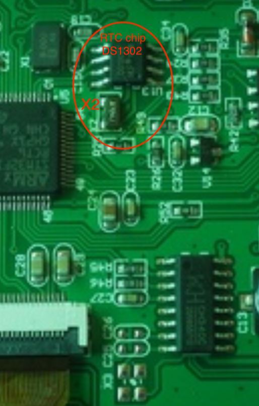
can you zoom in on the RTC of this unit in higher resolution? My GMC-500+ RTC does not function, maybe X-tal forgotten or loose.
see my other thread on this subject: "GMC-500+ RTC HW or FW issue? " |
To bug or not debug, that is the Q |
|
|
| Reply #10
Stargazer 40
USA
431 Posts |
Posted - 11/07/2018 : 15:58:52
|
Here is fuzzy pic of closeup of Xtal areas. X2 in your image if there is on other side of board? Here obviously is an X2 component soldered in.
Image Insert:

49180 bytes
Note that this is 500+V1. |
Stargazer 40 |
|
|
| Reply #11
donghelan
Japan
65 Posts |
Posted - 11/07/2018 : 16:11:13
|
Cool! Thanx it is missing! See my high resolution picture in the fore mentioned thread  |
To bug or not debug, that is the Q |
|
|
| Reply #12
donghelan
Japan
65 Posts |
Posted - 11/08/2018 : 16:35:53
|
quote:
Originally posted by Stargazer 40
Here is fuzzy pic of closeup of Xtal areas. X2 in your image if there is on other side of board? Here obviously is an X2 component soldered in.
Image Insert:
52199 bytes
Note that this is 500+V1.
Thanks again, Stargazer 40 for helping me pin pointing the problem with an incomplete "Monday morning" Geiger counter 
|
To bug or not debug, that is the Q |
|
|
| Reply #13
ikerrg
United Kingdom
334 Posts |
Posted - 11/09/2018 : 09:56:06
|
I have just installed the new firmware version for the 500+ V1 (1.24) and V2 (2.02) including the dead count correction and the auto voltage adjustment. Everything that I have checked looks good so far. Sadly, for now I cannot test any of the new features for now because the maximum setting for the dead time is limited to 500 microseconds, and with that setting I would still need a strong radiation source to see a noticeable change in the count rate. Regarding the auto voltage adjustment, it is even worse, because I would need at least 500 CPS to see the effect. I am not saying that the limits for those settings are wrong, I am just saying that I do not have a radiation source strong enough to test the new firmware additions by changing the settings to the maximum values. So I think we need your strong radiation sources here, Stargazer_40! Please, do the same measurements with and without the dead time in the M4011 tube to see if the algorithm is working as expected. Check if what it is logged to the internal memory (CPS) is the corrected or the uncorrected values, as GQ may have missed that part of the code (just trying to find bugs, not blaming anyone here ;).
There are still a couple of unfixed problems (not completely firmware related) that we reported some time ago:
-The conversion to .csv in the DataViewer 2.54 software has been failing the last times I have tested it (see my posts about the measurements in planes, e.g. http://www.gqelectronicsllc.com/forum/topic.asp?TOPIC_ID=5416 , reply #37). Have you found the reason of the problem?
-It might be related to the previous: have you fixed what ullix said about the 55 AA 02 code being used for �Note/Location text� which was changed to define a �triple data byte� in the new 4 byte firmwares? All the discussion is in http://www.gqelectronicsllc.com/forum/topic.asp?TOPIC_ID=5331 , starting at reply #41. That could be causing the problem in DataViewer when interpreting high CPM/CPS counts.
And to finish, I would like to say that the CPM threshold for medium and high radiation level indications are defined for both tubes at once. It is just a cosmetic thing that I do not pay too much attention to, but it should be possible to set some different values for both tubes independently, or set the values in uSv/h (so the adequate conversion for each tube is already included). At present, if you select the low sensitivity tube, you should also change those thresholds so their values make sense.
|
|
|
| Reply #14
ikerrg
United Kingdom
334 Posts |
Posted - 11/09/2018 : 10:20:34
|
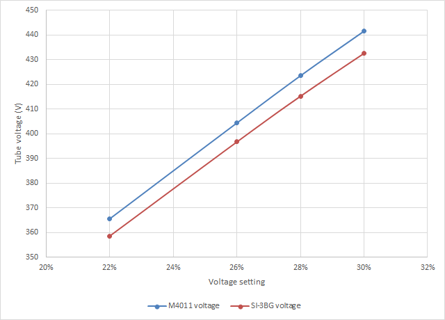
I was checking the voltages of my 500+ V2 at the different percentage settings. I got the following graph:
Image Insert:
17546 bytes
So it is a pretty linear behaviour up to 30% (about 9.5 V per each percentage increase), at least with the circuit under no load (negligible counts). Is that percentage related to the duty cycle of the switching to create the high voltage in the power supply? I suppose it will become very nonlinear above some percentage, or when the tube is under heavy count rate, which makes very difficult to estimate what is a sensible value for the auto voltage adjustment. I have set it to 2% per every 500 CPS, but I cannot test its effect.
|
Edited by - ikerrg on 11/09/2018 15:06:46 |
|
|
| Reply #15
Stargazer 40
USA
431 Posts |
Posted - 11/09/2018 : 12:51:30
|
@ikerrg, I am still waiting for firmware for majority of my counters to test. I went ahead and acquired a 600+ to get a direct comparison to the Mazur 9000, and that is the first one with the new firmware. I am very pleased to report that the counts dead time corrected are right on my spreadsheet calculations AND very close match to Mazur 9000 (throughout its range), so they employ a similar approach although they do not indicate so in any of their literature. I haven't had time to do more than make a few quick tests, but I have already been really happy with results. I will present dead time correction results first and then tackle the auto voltage. I was hoping that the Medium-High reading threshold would be like the Alarm threshold with either CPM, mR/h or uSv/h, but from what you're saying it isn't. I'll check that too of course. Like you I am crunched for time at the moment. Also with more than one meter and different tubes I am looking to calibrate them all during testing to match the 600+ via the calibrated Mazur 9000. Much more to come.
|
Stargazer 40 |
Edited by - Stargazer 40 on 11/09/2018 14:16:00 |
|
|
| Reply #16
ikerrg
United Kingdom
334 Posts |
Posted - 11/09/2018 : 15:06:55
|
| Looking forward to seeing your results with and without the dead time correction. For 100 kCPM you should be getting quite a strong correction! |
|
|
| Reply #17
Stargazer 40
USA
431 Posts |
Posted - 11/09/2018 : 17:25:21
|
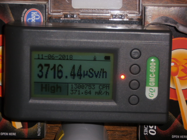
The GQ meters are doing great. Here's a pic of the 600+ as close as I can get to the infinity point on the dead time correction.
Image Insert:
457261 bytes
Dead Time is around a little more than 250. This is three times the range of the Mazur 9000. Actual CPM was 199,865CPM. I didn't get a pic of that but I will. Working with GQ on power supply check, the 7317 wouldn't go above about 230,000CPM no matter how much current was supplied. So tube had to be dead timed out. I think I am low on dead time and while GQ measured 248usec, I think that it's likely 260-265 to give a near perfect match to Mazur at the lower range limitation of the 9000 (.01-1250uSv/h).
All the meters are running the dead time/auto voltage firmware now so will make a lot of progress this weekend. |
Stargazer 40 |
Edited by - Stargazer 40 on 11/09/2018 19:04:25 |
|
|
| Reply #18
ikerrg
United Kingdom
334 Posts |
Posted - 11/10/2018 : 12:06:49
|
I have found a bug in the new firmware. It is related to the medium/high threshold setting. The setting goes up by 1000 and down by 50, so the setting has to be always a multiple of 50 (in principle). But if you go up to the upper limit of 65535, the setting jumps backwards and the number is not anymore multiple of 50. From then on, it is impossible to get back the multiples of 50 unless you reset the counter and reconfigure it again. You could fix this by setting an upper limit which is multiple of 50 (like 65000).
On the other hand, I miss the possibility to easily reconfigure the counter with a set of bespoke parameters after a reset or a firmware update. It is a pain having to go through all the menus to set the parameters to the desired values. Currently only the wifi configuration and the calibration is relatively easy to do, but not the dead times, the thresholds, the voltages, etc. There should be a way (e.g. in DataViewer) to export the counter configuration to a text file which can later be imported and parsed to upload the configuration, being compatible to any new firmware version because the DataViewer is doing the parsing.
|
|
|
| Reply #19
Stargazer 40
USA
431 Posts |
Posted - 11/10/2018 : 16:43:02
|
quote:
Originally posted by ikerrg
I have found a bug in the new firmware. It is related to the medium/high threshold setting. The setting goes up by 1000 and down by 50, so the setting has to be always a multiple of 50 (in principle). But if you go up to the upper limit of 65535, the setting jumps backwards and the number is not anymore multiple of 50. From then on, it is impossible to get back the multiples of 50 unless you reset the counter and reconfigure it again. You could fix this by setting an upper limit which is multiple of 50 (like 65000).
This can happen with all of the up arrow 10X and down arrow 1X parameter adjustments. Once you go past the top end the next placeholder to the right becomes the new digit at the bottom and you are stuck with it unless it's the least significant digit. So a cap that keeps it in the round numbers would be a good thing.
I want to thank you for fixing the menu rotation on the 600 series so that you can rotate from top to bottom or bottom to top in one button push. |
Stargazer 40 |
Edited by - Stargazer 40 on 11/10/2018 16:44:47 |
|
|
| Reply #20
EmfDev
2415 Posts |
Posted - 11/12/2018 : 10:15:56
|
@ikerrg, this will be fixed in the next firmware update so the numbers will always be multiples of 50 and with max 65000.
@Stargazer_40, we thought you didn't like that looping through the menu XD. |
|
|
| Reply #21
ikerrg
United Kingdom
334 Posts |
Posted - 11/12/2018 : 11:55:23
|
@EmfDev: Any comments on the "unfixed problems" I reported in reply #13?
|
Edited by - ikerrg on 11/12/2018 11:55:34 |
|
|
| Reply #22
EmfDev
2415 Posts |
Posted - 11/12/2018 : 12:12:33
|
@ikerrg,
. Looks like the plane data issue is caused by the data viewer software. Someone else is working on that one.
. It's weird that 500/+ implements
0 = date time,
1 = double byte,
2 = location data,
3 = three bytes,
4 = four bytes,
but 600/+'s implementations is
0 = date time,
1 = double byte,
2 = three bytes,
3 = four bytes,
4 = location data,
will now change 600/+ implementation to same as 500/500+. This change will be included in the next firmware update. Not sure when it's going to be released.
Also in the current 500/+, if you see a 55 AA 05, that is tube type, and 00 = both, 1 = tube 1, and 2 is tube 2.
As for the medium/high threshold, we will keep it as of right now |
Edited by - EmfDev on 11/12/2018 12:13:22 |
|
|
| Reply #23
ikerrg
United Kingdom
334 Posts |
Posted - 11/12/2018 : 14:13:57
|
| Thanks EmfDev. That information is key for ullix and GeigerLog, including the new code (55AA05). I hope this homogenizes the output of all the 4 byte firmwares not to depend on the firmware version to know how to parse the data. |
|
|
| Reply #24
ikerrg
United Kingdom
334 Posts |
Posted - 11/14/2018 : 05:23:53
|
@EmfDev: So now that the dead time is finally implemented and seems to be working (thanks to GQ for listening to us and to Stargazer_40 for testing), the next thing is to get rid of the sum of counts when both tubes are being selected in the 500+. I already proposed how to do it in my spreadsheet, by combining the counts based on the statistical approach and the ratio of sensitivities for both tubes, but acting only on the counts, not on the dose rate in uSv/h (that is later calculated from the combined counts using the famous 0.0065 calibration of the M4011 tube). That only affects to the readings when both tubes are selected (what we called "auto" mode). It is the last remaining bit that just makes no sense in the device (to add the counts of both tubes!), and it is easily fixable in the firmware.
Well, it is the last remaining bit apart from the 3 point calibration, which is almost useless now but it makes no harm.
|
Edited by - ikerrg on 11/14/2018 06:29:43 |
|
|
| Reply #25
EmfDev
2415 Posts |
Posted - 11/14/2018 : 11:05:59
|
| @ikerrg, I was trying to implement this one and actually realized that the usv calculation is based from that cpm value for both tube and assumed that they were added so it's not that straightforward. Right now, I'll need more time to implement this one and then test it. So this might become available in the future. |
|
|
| Reply #26
ikerrg
United Kingdom
334 Posts |
Posted - 11/14/2018 : 11:50:04
|
Yes, currently the dose rate in uSv/h for the two tube mode (auto mode) is calculated using ullix�s proposed algorithm, but the CPM is still the sum of both tubes. So you need to reprogram the algorithm as I propose in replies #34 and #38 at http://www.gqelectronicsllc.com/forum/topic.asp?TOPIC_ID=5461&whichpage=1
Obviously, that requires thorough testing after implementation. In fact, now that we have the dead time of the M4011 tube set by the user, we can limit the automatic algorithm to work until 90% of the maximum CPS of the M4011 tube (0.9*1/deadtime), and then automatically switch to the other tube. In any case, even if you don�t add that switching, the result will be better than the current addition of CPMs.
|
|
|
| Reply #27
EmfDev
2415 Posts |
Posted - 11/14/2018 : 12:29:10
|
Yes the uSv is based on ullix's algorithm but it is also using the CPM which is is the result of 2 tubes being added together. But in the uSv calculation, the CPM is divided into two. So if I changed the CPM that is added together, then I'll have to modify again the uSv calculation to not assume that that the CPM is added together. That's why it's not straightforward.
The code right now doesn't automatically switch when the CPM of tube one is 90% or higher. It just caps the CPM to 1/Deadtime - 1
so that it doesn't become negative. And that's going to be a really high number anyway and will use both tube counds in the uSv calculation. |
|
|
|
Topic |
|