| T O P I C R E V I E W |
| ZLM |
Posted - 05/13/2013 : 20:36:23
There are two ways to measure the voltage on GMC-080, GMC-200, GMC-280, GMC-300, GMC-320 tube:
1. Use a 10M ohm mutimeter 1000V range to check the voltage on tube two ends. For 380-450V, the meter should read about 180V.
2. To get better accuracy voltage reading, use following way. This is a generic method and it should work on most high voltage citcuit:
You need a regular 10M ohm internal resistance multimeter. Serial a 1G ohm resistor on your multimeter prob. Read the voltage frm the multimeter with 20V range.
And then calculate the actual voltage by following formular:
V(actual) = V(DMM read) x ((R(meter ohm) + R(probe ohm)) / R(meter ohm))
Here:
Voltage = V(reading from multimeter) * 91.9
if your multimeter reading is 4.2V, then the actual voltage is 4.2*91.1 = 382.62V
|
| 23 L A T E S T R E P L I E S (Newest First) |
| ullix |
Posted - 02/15/2023 : 23:23:50
@jonescruzz: Actually the main problem is the internal resistance of the High-Voltage-Generator. This is in the order of 10...20 MOhm, and thus requires an instrument with its internal resistance much greater than this.
As such an instrument is not available for most users, you need an external resistor to your regular DVM of something like 1 GigaOhm.
|
| EmfDev |
Posted - 08/22/2019 : 11:17:23
That might be to increase the voltage of both tubes to be a little farther from the lower end of the recommended voltage. |
| Geo-Johnny |
Posted - 08/22/2019 : 10:46:31
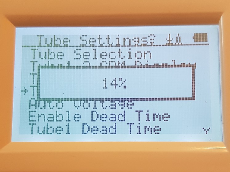
Yes, but in the default settings of the new Firmware Re 2.13 of the GMC500+, which I received a few minutes ago from the support, the voltage of both counter tubes was increased by 1%.
Tube 1 = default 16% and Tube 2 = default 15% |
| EmfDev |
Posted - 08/22/2019 : 09:23:59
Yes, that looks like the voltage divider for voltage on board reading. |
| Geo-Johnny |
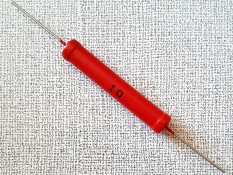
Posted - 08/22/2019 : 07:56:51
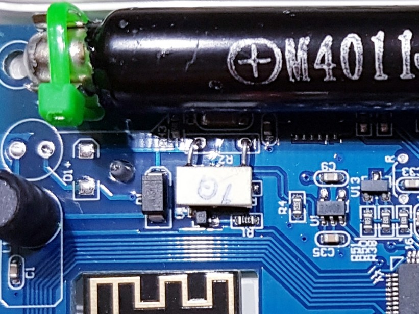
If you look closely at the board of the GMC500+, you will find a white plate labeled 1G in the high voltage range of the counter tube 1 (M4011). This is the measuring resistor for the internal voltage measurement of the GMC. In the middle of the picture ...
GMC500+ Measuring Resistor 1GOhm:
 |
| Geo-Johnny |
Posted - 08/22/2019 : 03:13:10
The same thing I did with the second counter tube of the GMC500+ ...
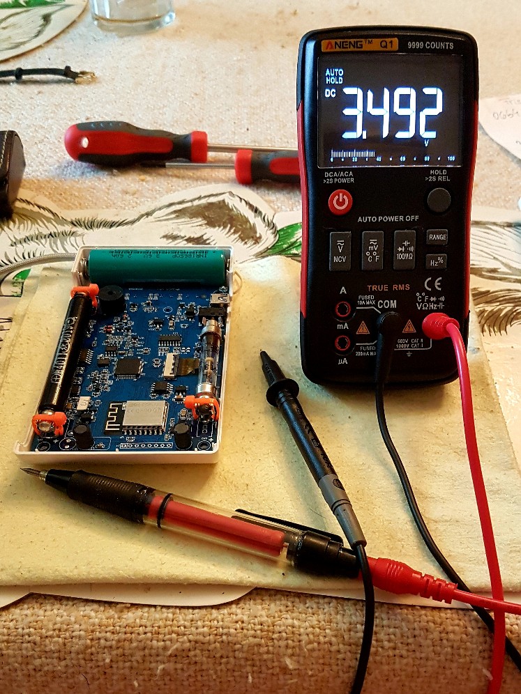
GMC500+ TUBE 2 (Unfortunately without voltage display  ) )
Digital Multi Meter (DMM) 10MOhm Impedance
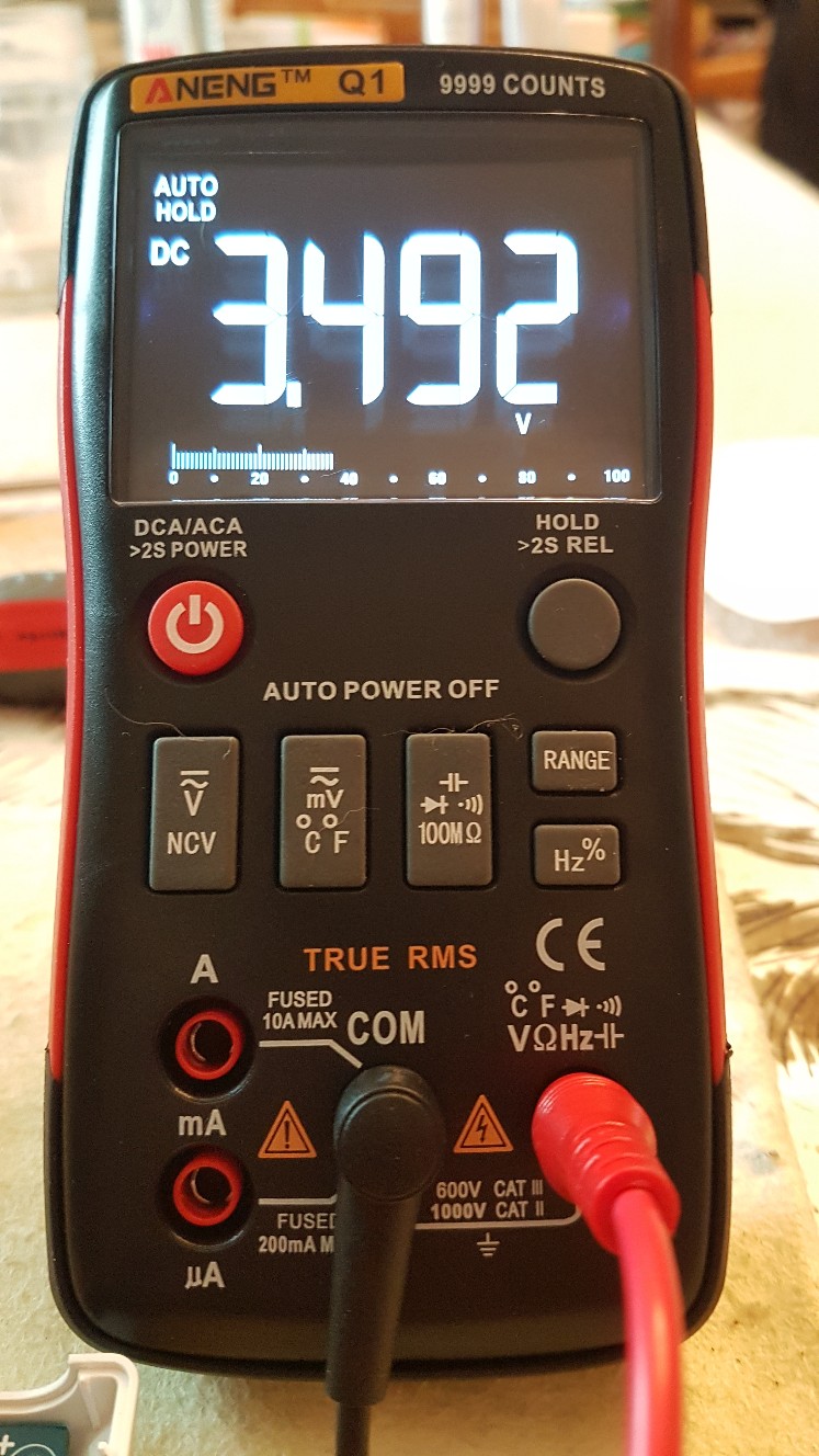
3,492V * 101 = 352,692V ~ 353 Volt on Counter Tube 2.
Equipment and GMC500+ open
 |
| EmfDev |
Posted - 08/21/2019 : 14:47:11
That's great! Gives us more confidence on the on board voltage reading. Thanks :) |
| Geo-Johnny |
Posted - 08/21/2019 : 12:53:02
My measurements with the probe as a voltage divider on a GMC500+ gave pretty accurate values. ...
GMC500+ TUBE 1
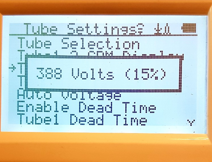
According to the above formula - (R[Probe] + R[DMM]) / R[DMM] = ratio factor, ie (1000MOhm + 10MOhm) / 10MOhm = 101 * U[DMM] = U[counter tube]
Digital Multi Meter (DMM) 10MOhm Impedance
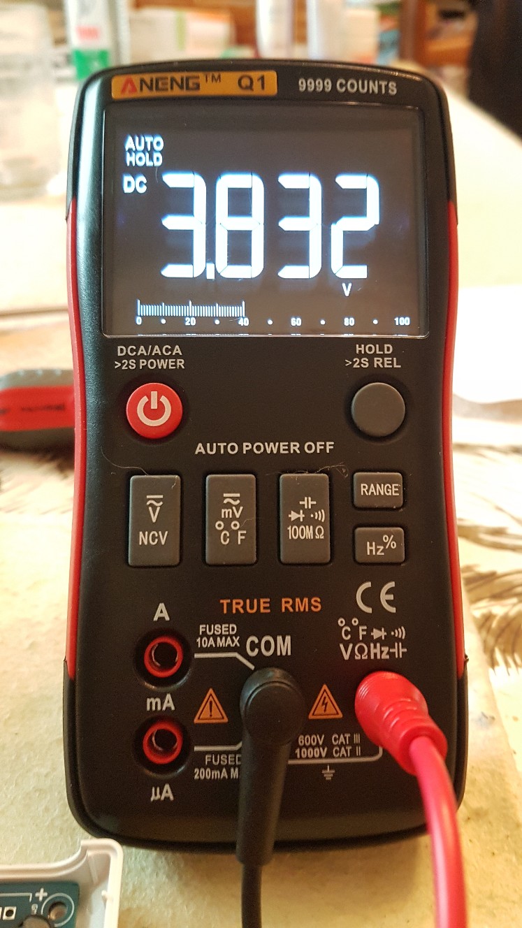
3,832V * 101 = 387,032V ~ 387 Volt on Counter Tube 1 |
| Geo-Johnny |
Posted - 08/20/2019 : 10:56:11
Today I finally got my 1GigaOhm resistor and immediately built a probe for my multimeter. The case was an old ballpoint pen ...
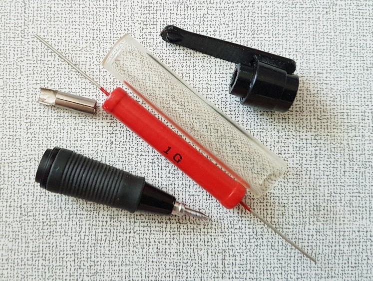
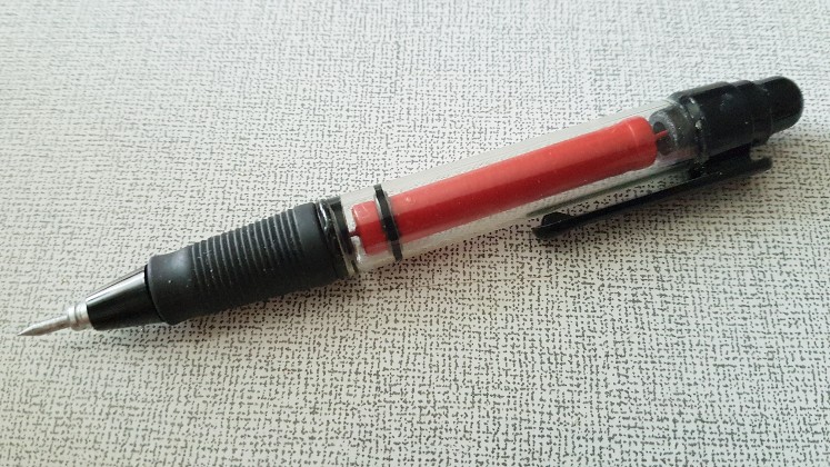
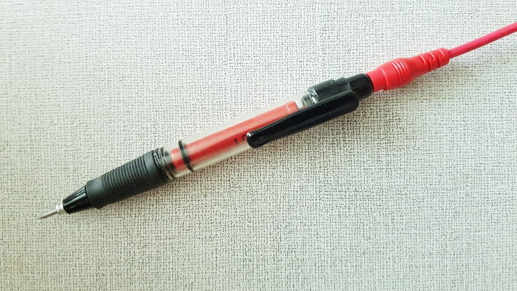
Sequel follows ... |
| Damien68 |
Posted - 08/19/2019 : 01:07:00
to measure the high voltage on Geiger-Muller tube, do not measure it directly on the two pads of the tube, because there is an anode resistance of about 4-10 MOhms in series on the power supply. which explains why the voltage drops when measured directly with a 10 Mohms impedance meter.
Powering tube with CCFL transformer in principle should decrease the consumption of power supply stage if it well tuned and so increase the battery life, but this should not change the reliability of the whole.
Try to measure High voltage before the anode resistor.
|
| donghelan |
Posted - 11/11/2018 : 07:36:50
Ullix, of course you are right that the values of my old probe's resistors are too low now if 4 microAmpere is too high for this HV supply design.
For this case that 4 microAmp @400V is too high due to the HV source limitation, suggest to make a divide by 100 for the DMM, to read 400V as 4V:
Select a 1 GOhm 1% resistor of 990 MOhm (-1%). No further calculations needed as in the previous lower impedance design.
Add 9 MOhm for divide-by-1000 with a 1 MOhm scope attached, to read the value as 400mV at 400V input.
The main advantage of HV supply designs that use transformers (having lower output impedance) is that it is not required to have measurement devices which such high impedance.
Unfortunately HV power supplies with low output impedance are a bit more bulky using a transformer.
In the proposed example measurement circuit for HV supply with low output impedance, the HV source is only measured.
When you measure the voltage over the tube then can leave out about one 4.7MOhm resistor due to the current limiting resistor for the Geiger tube (3~6 MOhm usually).
The attached low impedance HV supply design is tested successfully by "Radgoes" in 2011.
Image Insert:
86200 bytes |
| ullix |
Posted - 11/11/2018 : 05:24:25
This is a possible way of designing a probe, but its value of about 100MOhm does result in a current of several �A, and whether this is acceptable or not does depend on your question you want to have answered. I think for the purposes recetnly discussed, it does draw TOO MUCH current!
Your external circuit consists of 90MOhm plus two times 10MOhm in parallel (from the 2 instruments) giving a total of 95MOhm.
Then we need to consider the internal resistance of the HV generator, which I had determined as something between 10 and 20MOhm for the counters considered for a total resistnace of 105...115 MOhm.
Let's round the total down to 100MOhm and use an HV-generator-internal-voltage of 400V to ease calculation. This results in a current of 4�A.
Thus the voltage drop at the INTERNAL resistance is 4�A * 10MOhm = 40V up to 4�A * 20MOhm=80V.
Such a drop of 40...80V could mean that the set voltage drops from Geiger tube plateau midpoint to below the lowest voltage still triggering any counts!
I'd say you need to be higher in your external resistance by at least one magnitude, which brings you to the 1 GigaOhm resistance to be put before the instruments. That is why this value of 1 GigOhm had been used in many tests recently. See http://www.gqelectronicsllc.com/forum/topic.asp?TOPIC_ID=5369 Reply #15
With 1 GigaOhm the difference between intrinsic voltage of the HV gen and measured voltage is roughly in the 10V region. And even that difference should be kept in mind when HV is discussed!
|
| donghelan |
Posted - 11/09/2018 : 07:14:23
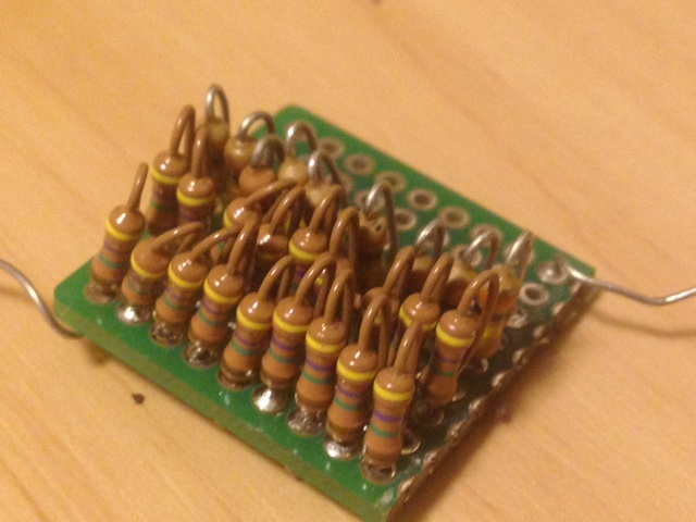
This is a divide-by-10 probe example made in 2011. just after the Fukushima NPP1 disaster here in Japan.
The HV supply in an old cold war era(1968) German army geiger counter was broken due to faulty Capacitor causing short circuit, then you need something like this from the shelf to verify the Voltage after Capacitor replacement.
Capacitors are the most likely components to fail actually in HV circuitry.
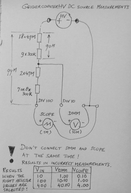
The probe is made of 18x 4.7 MOhm and 9x 300 KOhm, 5% tolerance(gold) resistors all in series soldered.
Calculated value: 87.3 MOhm.
Real Value: 90 MOhm.
You have to test this "trial and error" until you measure 1.0V (Real 1.023V) when supplying 10VDC via the probe under construction.
When measuring 400V from a Geiger counter's HV supply my Metex M-4630 DMM (10MOhm impedance) will read about 40V.
A current of 4 microAmpere drawn from the HV supply appeared to be acceptable in this case.
Probe modification for 1 MOhm impedance Oscilloscopes
If you use an Oscilloscope with an impedance of 1 MegaOhm you can extend this probe until you get 99 MegaOhm to have a divide-by-100 probe that still draws 4 microAmpere from the HV supply.
E.g. add 2x 4.7 MOhm plus a 7~8 extra 300KOhm resistors to the chain based on the previously calculated value 87.3 MOhm because your selection of resistors might have completely different values.
Trial and error until you read 100 mV (25mV per division or something) on your scope at exactly 10VDC input.
A Analog Devices LT1236ACS8-10 VREF chip with 2ppm/C Temperature Coefficient, 0.05% initial accuracy, will be a good 10V reference for calibrating your probe.
Cheaper Maxim alternative: MAX876AESA+ Maximum Temperature coefficient 7ppm/C, initial accuracy � 0.03%
See basic circuit of measuring HV DC sources below but don't connect both Oscilloscope and DMM at the same time because this will give incorrect results due to the parallel circuit impedances of the two measurement devices.
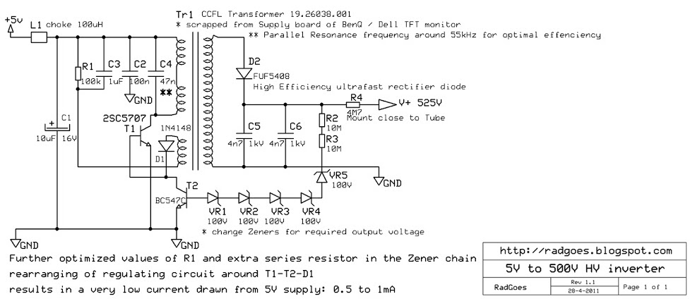
Other Efficient HV DC source designs
For those amongst us who want to experiment with HV supply design themselves I recommend this design from The Netherlands by "Radgoes" as a very efficient example but more suitable for stationary Radiation monitoring (delete the spaces in h t t p)
h t t p://radgoes.blogspot.com/2011/04/hv-inverter-circuit-for-geiger-mueller.html
Image Insert:
102075 bytes
Image Insert:
80232 bytes |
| ZLM |
Posted - 08/12/2018 : 10:07:46
It should be 10 Megaohm. |
| ricardoalegret |
Posted - 05/23/2018 : 12:24:56
Hi, your method ZLM to measure high voltage with very low currents is very interesting, my question is, what multimeter has an impedance of 11 megaohm, mine have 10 megaohm.
thanks and regards |
| rogerroentgen |
Posted - 05/01/2016 : 21:56:44
quote:
Nudnik Posted - 03/08/2016 : 00:03:22 Can I use a oscilloscope with a 10:1 probe? E.g. DSO nano?
a 100x probe would probably be safest to check voltages at the tube. |
| Nudnik |
Posted - 03/08/2016 : 00:03:22
Can I use a oscilloscope with a 10:1 probe? E.g. DSO nano? |
| F_Schro |
Posted - 11/10/2015 : 09:53:45
Craig; is it that the tubes are "touchy" about capacitance or is it the loading on the DC-DC converter that drops the voltage ?
In either case ZLM's method should work fine (1G series)as long as the
resistor doesn't have too much parasitic capacitance. Some HV resistors with the single serpentine type element can be 5-10pF.
You can decrease the effective cap by several R's in series but hard to find higher than 20M in the smaller resistors. |
| ZLM |
Posted - 05/20/2014 : 15:39:08
No. The tube has much higher resistance. You do not have to remove it. |
| Benezi |
Posted - 05/16/2014 : 07:54:34
Do I have to remove the tube for the exact method?
Regards, Benedikt |
| Craig |
Posted - 10/28/2013 : 21:40:44
* I don't know about the M4011, but some G-M tubes are very touchy about added external capacitance. Legend has it that the capacitance between your meter's test leads (as much as 20pf) can take out some G-M tubes. _That_ is the reason for the "minimum anode resistor" specification (frequently: 4.7 meg-ohms), since any capacitance on the other side of that won't hurt the tube.
Consequently, the suggestion here to measure anode voltage through a stand-off resistor at the end of your meter's probe is excellent advice.
If you have a 100 meg-ohm resistor (or make one out of 10 10M resistors), keep it clean and calculate what's on the anode side of that resistor per the ratio: meter resistance + 100M divided by the meter resistance. Example{ 10M + 100M / 10M = multiply display by 11x.
For better accuracy, add another 4% to the example --due to the 110M load against the 4.7M circuit board anode resistor (if that's what it is, and assuming you're touching down on the G-M anode). |
| ZLM |
Posted - 10/20/2013 : 21:02:57
To get accurate voltage, use above formular to calculate.
The 140V-150V is measured directly by a regular 11M digital multimeter on a 1000V range position. |
| Frank |
Posted - 10/10/2013 : 15:21:18
When it says check the voltage on the tube ends, is that installed, powered up and for a required tube voltage of 380-450, you should measure around 180V? I have a 4011 tube from here, voltage range for this tube ? so I should be setting it too ? |