| T O P I C R E V I E W |
| ullix |
Posted - 07/22/2017 : 03:49:55
I'd like to take a look at the shape of the pulses generated by the tube using an oscilloscope. At what point in the circuitry can I place my 10x (10MOhm) probe with minimal impact on the shape of the pulse while still getting a signal representing this pulse?
The audio out is one option (it works), but I doubt this signal has anything to do with the original one?
|
| 23 L A T E S T R E P L I E S (Newest First) |
| ullix |
Posted - 08/04/2017 : 08:39:54
Phil, thanks, but be assured I already took advantage of your documentation! People should be reminded that they can find your stuff here: https://sourceforge.net/projects/gqgmc/files/gqgmc/
This collection was essential for programming GeigerLog!
But as good as the theory document is, it doesn't answer the questions with respect to a specific device and tube. However, I think the relevant stuff is known now. I am currently taking a look at the "calibration" now that the pulse width is known and will post.
|
| phgphd |
Posted - 08/03/2017 : 14:59:55
Ullix, take a look at the PDF file, Geiger_Tube_theory.pdf, which is part of my gqgmc source forge project. It contains a detailed discussion of typical circuits used with Geiger-Muller tubes and such circuit characteristics as dead time and quench time and shows example waveforms (Fig 18). Your questions may be answered. |
| ChrisLX200 |
Posted - 07/28/2017 : 04:11:57
OK well, I cut another piece of cable about the same length. I fed a 1KHz 5V square pulse direct to the scope probe and it looks like this:
Image Insert:

1536054 bytes
Then with the cable between the source and scope probe:
Image Insert:
1536054 bytes
A 56pf capacitor does really bad things!
Image Insert:
1536054 bytes |
| ChrisLX200 |
Posted - 07/28/2017 : 03:28:59
I'll check that. To get the OpenChice Desktop working with the Tek I needed to update it to the latest available firmware, which in turn required the use of four 3-1/2" floppy disks. Not having a 3-1/2" drive I had to buy one (amazingly cheap though, about 6 UKP for a plug-in USB drive).
Anyway, the alternative is use this driver:
Image Insert:
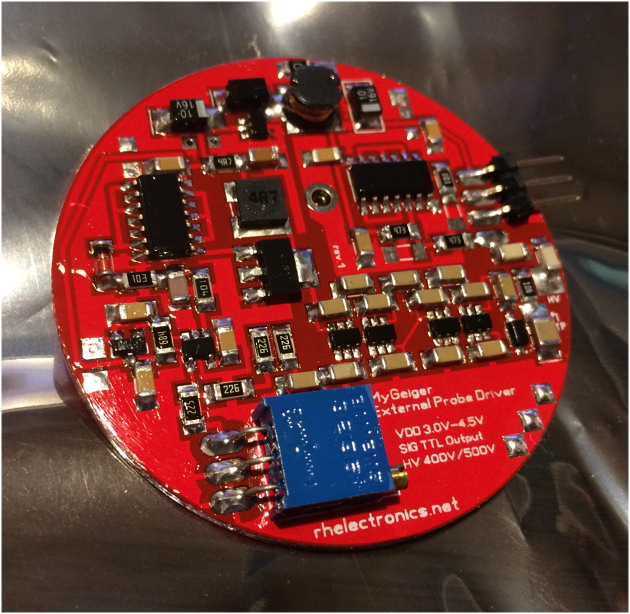
176102 bytes
This positioned right next to the probe, it converts the signal to pulses which can be read using a cable many meters long. Unfortunately I only have one such driver but several probes...
|
| ullix |
Posted - 07/28/2017 : 03:18:54
Now that is a scope!
quote:
(although the conductors are heavier gauge than any USB cable so hopefully not so much of a problem).
I think the gauge does not matter at all, it is rather the distance between the two wires, which increases capacity. Remember that C is proportional to 1/distance of the two plates of a capacitor.
Example: Due to a lack of short lab cords, I used two long ones of 1.5m each. The length was coiled up near the counter, the coils being apart by the with of the counter. No obvious influence on the pulse width. Then the coils were laid on top of each other, which would increase capacity. And sure enough, pulses were clearly widened!
Try to measure capacity of your cable with a DVM (one end in the DVM, the other open, no tube connected. You should be able to distinguish between 100pF and 10pF. I suspect it will be near 100pF.
Perhaps your scope can do it too: feed rectangle to input and shunt with cable or reference capacitors. Check for smoothening of rise or fall edge of rectangle. |
| ChrisLX200 |
Posted - 07/27/2017 : 12:03:55
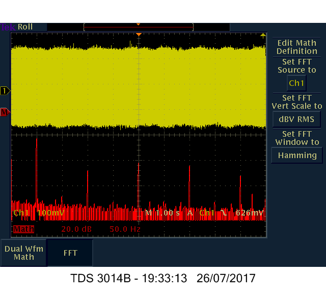
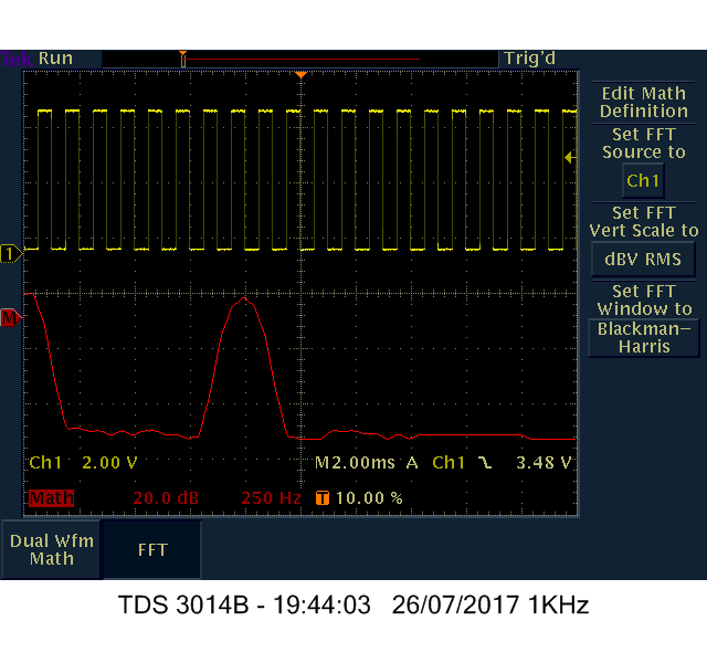
Excellent! Got the Tek OpenChoice Desktop working :-) Now I can save decent screen captures (they were pretty poor using the e*Scope function - the scope's built-in webpage). Maybe I can actually get on and check things now.
Just playing with the FFT function...
Image Insert:
1536054 bytes
Image Insert:
1536054 bytes
Image Insert:
1536054 bytes |
| ChrisLX200 |
Posted - 07/27/2017 : 11:28:57
Thanks for the heads-up on that issue. I measured the 4011 directly via the tabs soldered to the PCB, but my other dectector has a SBT-11A connected using a 1M length of dual-core silicone cable. That's now a worry (although the conductors are heavier gauge than any USB cable so hopefully not so much of a problem). |
| ullix |
Posted - 07/26/2017 : 03:36:53
I made a mistake by ignoring the capacitance of the leads to the tubes! As the counter - without modification - allows only to host one M4011, I had to attach the SBM20 and SBT11A tubes via some cables. Those cables increase the capacitance across the tube, resulting in lengthening of the pulses. The effect of capacitors connected from Anode to Cathode on a M4011 mounted in the counter case is shown in the picture. Beyond 15pF there is a clear deterioration of the signal.
Image Insert:
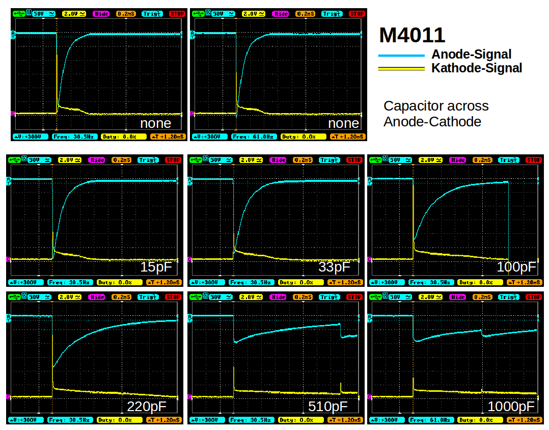
82127 bytes
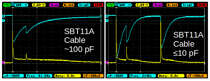
My DVM can measure capacitance only as nF with a resolution of 10pF, but the result is consistent with the observed pulse shapes in the scope. Some regular lab cables, thought to be poor, actually aren't so bad as long as one keeps the two leads well apart from each other to minimize capacitance. A cable soldered for the SBT11A using an old USB cable, however, turned out as having around 100pF. Such the pulse shapes observed were really poor at about 250�s, see previous posts.
Measured with the good old lab cables, the SBT11A might have been the fastest of the three tubes tested, perhaps withe a recovery time as short as 150�s. Compare capacitance impact in the next pic.
Image Insert:
16296 bytes
The SBM20 measurement was not impacted, those data are still valid.
Mind you, this is relevant only for very high count rates! At these capacitor values the count rate in the low to medium range is not impacted. |
| ChrisLX200 |
Posted - 07/25/2017 : 16:23:20
I'll take a look later. I've been trying to figure out how I might get a screen capture into the computer from the Tek, it does have a 3-1/2" floppy disk drive (if you can remember what they are) but none of my computers has one. I then noted it does have an ethernet port on the back which I'd never done anything with so I connected it to the network using that. Now I can get a screen grab (of sorts) which is a whole lot better than taking photos :-) |
| ullix |
Posted - 07/25/2017 : 03:19:29
@D-zombie: Thanks for the reminder.
Surprise: the audio signal is actually a good proxy for the anode signal!
Perhaps Chris can verify cathode, anode and audio; he has the better equipment.
Image Insert:
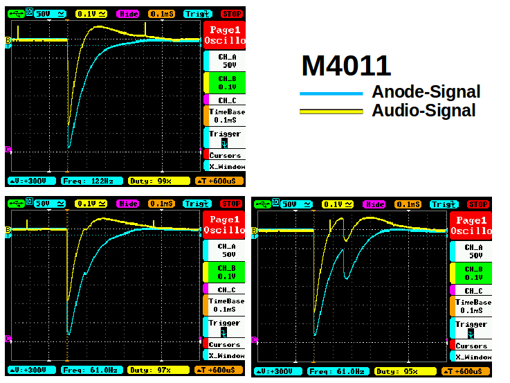
29680 bytes |
| ullix |
Posted - 07/25/2017 : 02:58:13
Aren't the GMC counters cathode-sensing? So I measured at the cathode too, and was surprised. Picture shows dual traces, blue taken at the anode, yellow at the cathode. The numbers at the top row in each little picture give volt and time for each of the 8x12 little grids.
The cathode signal is much faster - at half amplitude ~5�s as opposed to ~100�s at the anode (top 2 pics). But then the cathode signal has a long tail, matching the anode total pulse length of ~400�s.
How comes? I measured directly at cathode and anode, resp., there is no active signal shaping circuitry yet?
Anyway, bottom 6 pics show that at about 200�s - perhaps a bit earlier, like 190�s - the counter can detect the next pulse, consistent with previous observations.
Image Insert:
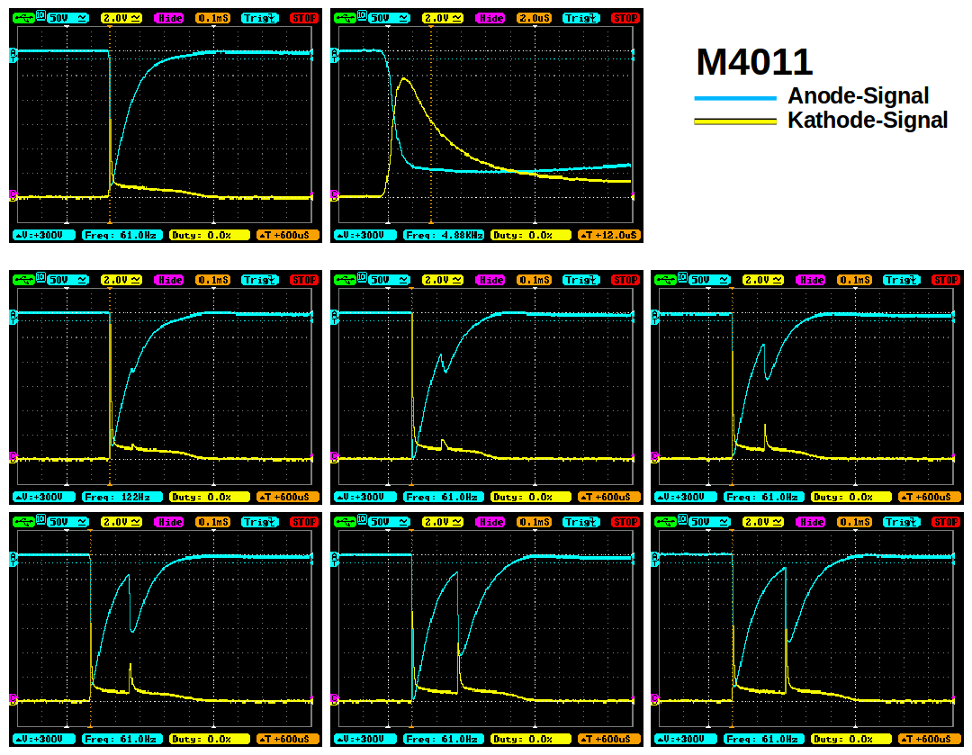
40480 bytes |
| Distelzombie |
Posted - 07/24/2017 : 08:33:53
No there is no value for the M4011 tube.
It's weird that you measure 3.2 times the recovery time with the sbt-11a. I think you need to increase the voltage a little when you use it.
It might also be that the same particle wave was going through more than one of the four section. They are separate. Hence the pin count. But I think this is no problem.
Can you compare the signal you measure on the tube with the audio signal? You need a three pole to four pole cable for this if you use the smartphone. (I was wrong in the email.) |
| ChrisLX200 |
Posted - 07/24/2017 : 08:21:17
I think much will depend on the PSU - what current it can supply to reverse the voltage drop will (to some extent) determine how fast it can recover, and of course the detector circuit will need to have a threshold set at which a subsequent count can be triggered. In my ignorance of these things I also never considered that some detectors use cathode-sensing rather than anode-sensing tube circuitry... |
| ullix |
Posted - 07/24/2017 : 04:39:24
@Dzombie: I am curious: does your list of dead times also have a value for the M4011?
It might be more appropriate to call these times the recovery time, as the tube dead time is only part of the total recovery time. The latter also depends on the electronic circuitry used in the counter. Relevant for the maximal measurable count rate is the recovery time.
So, with that caveat, with my GMC300E+ counter in my setup I found the tube M4011 being faster than the SBM20, and this faster than the SBT11A, see picture. Relative to my assessment of the M4011 having a recovery time of 200�s, the SBM20 will have 220�s, and the SBT11A 250�s.
Using an arbitrary 100% as average for the amplitudes of the pulses, the M4011 and SBM20 vary between 60 and 110%, while the SBT11A is only between 40 and 80%, i.e. pulses are notably smaller.
The highest count rates would thus be measurable with the M4011, compared to the other tubes. However, I think this difference is solidly irrelevant for anyone using the GMC counters.
With those numbers on recovery times I can now calculate the theoretical correction curves, though it would still be of interest to compare them with real-world, very high count rates.
Image Insert:

49489 bytes |
| Distelzombie |
Posted - 07/23/2017 : 21:49:02
A list of deadtimes from different tubes in ys, for comparison:
Ludlum 44-9 = 80
LND 712 = 90
LND 7312 = 40
SBM-20 = 190
SBT 10 = 50
SBT 11(a) = 80
SI 8B = 160
SI29BG = 95
STS5 = 190
VA-Z-115.1 = 150
GMT01 = 190
Ion chamber 1l = 10000
(Data from Radmeter app) |
| ullix |
Posted - 07/23/2017 : 05:41:11
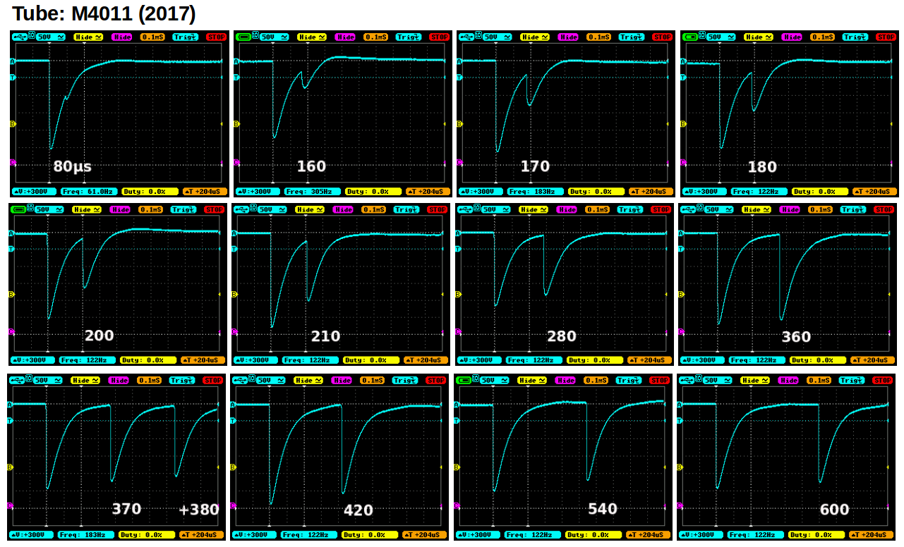
Encouraged by Chris' results I put a capacitor in series with my 10x (10MOhm, 600V) probe and connected the capacitor to the plus-end of the tube. GeigerLog logged in parallel and there was no impact on the count rate from using the probe. For capacitor I tried 1000pF, 4700pF and 394000pF. It did not seem to make any difference whatsoever; so I continued using 1000pF.
A gas mantle (Th source) was put very close to the tube, getting me near CPM=5000. Then I single triggered my scope and stored selected scope-screenshots with at least 2 events, with the 2nd pulse coming with different delays after the first.
The picture shows 12 shots, each having a trace of 1.2ms total. I succeeded only once to get 3 pulses on one shot (bottom left).
The big, white numbers give the approx. delay of the 2nd pulse to the first, ranging from 80�s to 600�s. After each "flash" the tube must recover, and this dead time seems to take longer than just the duration of the electric pulse. While I could not measure which pulses were also registered as counts, based on the shape of the 2nd pulse and the chance for detecting this electronically, my conclusion is that the total dead time is about 200�s.
This translates into a maximum theoretical count rate of CPS=5000. Given the Poisson distribution of the count rate, the real live limit is probably closer to CPS=4000, or CPM=240.000, or 1600�Sv/h. This is more than the counters can handle in CPM mode, and should anyway be reason for concern from a radioactive safety perspective!
Image Insert:
155462 bytes |
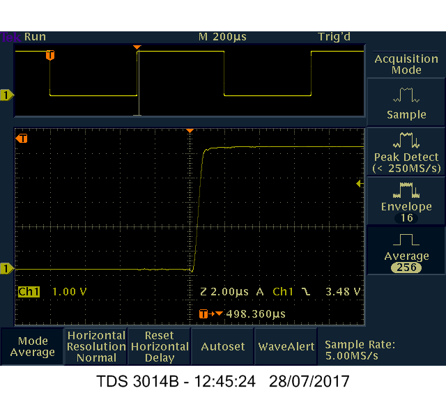
| ChrisLX200 |
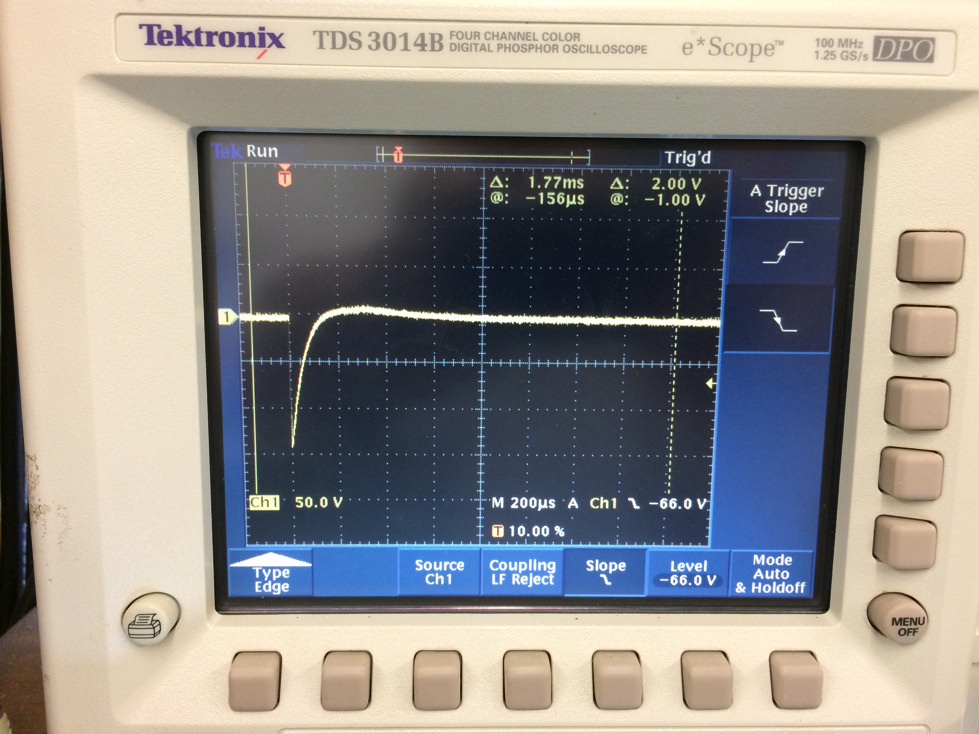
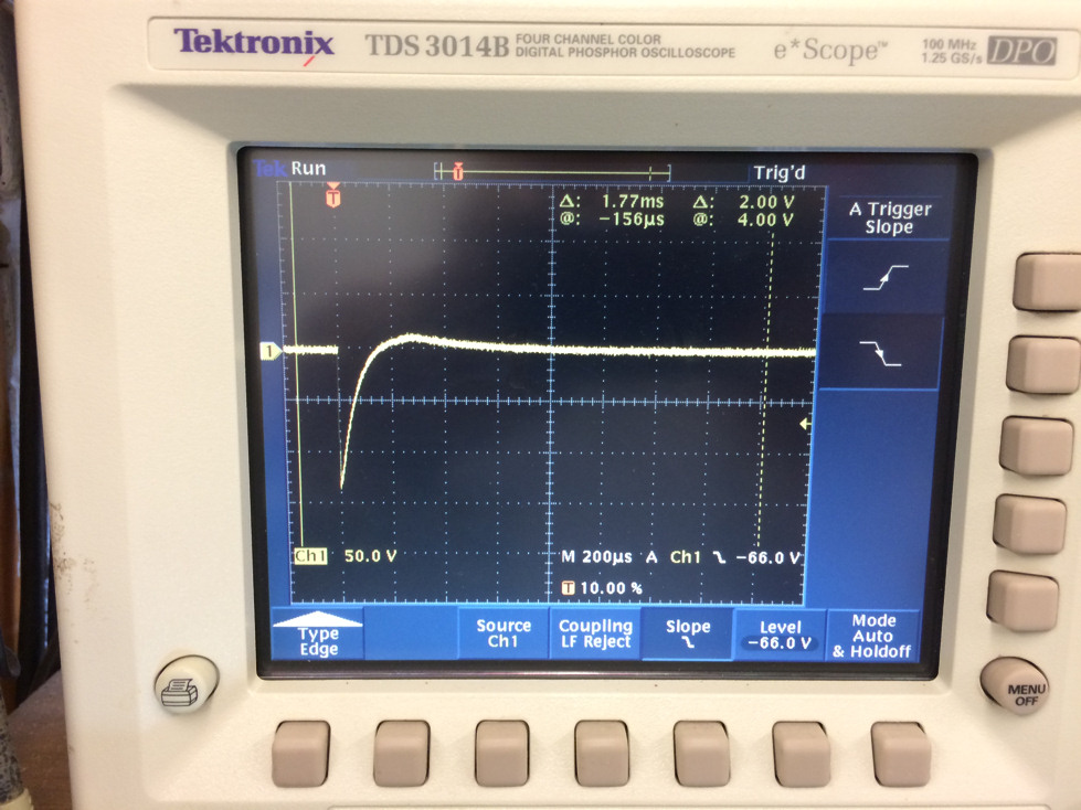
Posted - 07/22/2017 : 10:18:02
Timescale is 200uS per large square and voltage is 50v per large square, I shifted the resting potential (whatever it actually is - we already know you can't measure it correctly this way) up one square so the small arrow you see on the right is the trigger level set at -66v below resting potential. The pulse is about 100uS before full recovery (I would expect it may be a bit faster recovery without the 10MOhm probe attached). That would suggest a max of ~10,000 counts per sec (?) before it saturates, but again the presence of the probe will be distorting the result.
This was just a quick look - normal background gamma radiation probably. All spikes looked similar, I didn't try averaging though. Neither did I try a hot source and it's not sensitive to alpha of course. However the GM300+ was happily ticking away at the same background rate with or without the probe attached so it didn't seem to prevent it working at that low level, but the probe may well reduce the max CPS that could be recorded. |
| ullix |
Posted - 07/22/2017 : 09:28:41
oh-my-god, a real Tektronix! Let me quickly make a genuflection ;-)
I am not clear on the x-scale: what is the width of the pulse at the points where the pulse crosses the "X-axis" (the grid line with the tick marks on)?
And is this a typical width, or what is the scatter? Do you see a dependency on the type of radiation (alpha, beta, gamma)?
|
| ChrisLX200 |
Posted - 07/22/2017 : 08:47:57
quote:
Originally posted by ullix
Yes, but:
The tube has a very high ohmic resistance in normal state. During the "lightning strike" the resistance drops drastically. Since the power source can deliver only a limited amount of current the voltage across the tube collapses. The consequence is that you can't measure voltage very easily, see the sticky point above on voltage measurement http://www.gqelectronicsllc.com/forum/topic.asp?TOPIC_ID=3745
In fact, using a 10MOhm DVM to measure the ~400V gives you a readout of only ~150V, which is below the level where radioactivity could trigger another count. As my oscilloscope probe also has only 10MOhm, I would thus never see a pulse!
I believe putting the probe directly at the tube is the one place where it definitely will not work. Perhaps I can follow the guidance from the sticky point and put a very high Ohm resistor in series with my probe, but then I may get a different distortion of the signal by RC effects in the probe/oscilloscope circuitry.
I suspect the count signal will be delivered from the tube through a capacitor to the detecting circuits, and this may be a place where I could scavenge the signal. But I don't know if there is a capacitor and if so, which one it is.
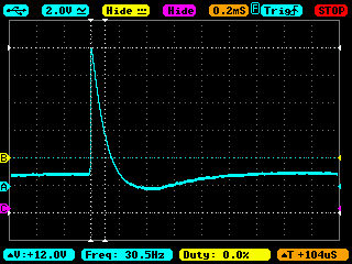
As a bit of a spoiler I am attaching a osci screen shot taken taken at the audio jack. It has the form I expect for the real signal and a width of only ~100�s. But this could be the result of who-knows-what circuitry.
Yes I read that sticky. The signal from the tube will be a negative 'pulse' not positive. That has first to be detected and converted/processed into a sensible positive volatage spike (having sufficient current) that can be output as the audio signal.
Well you made me go look with my own 'scope :) Sorry but mine does not connect to a PC so I took a quick photo. This is connecting direct to the +ive probe terminal using a 100MOhm probe (rated @ 500V). As expected the signal is a voltage drop, I see about -145v using this probe. Two examples..
Image Insert:
216289 bytes
Image Insert:
202239 bytes |
| ullix |
Posted - 07/22/2017 : 07:21:28
Yes, but:
The tube has a very high ohmic resistance in normal state. During the "lightning strike" the resistance drops drastically. Since the power source can deliver only a limited amount of current the voltage across the tube collapses. The consequence is that you can't measure voltage very easily, see the sticky point above on voltage measurement http://www.gqelectronicsllc.com/forum/topic.asp?TOPIC_ID=3745
In fact, using a 10MOhm DVM to measure the ~400V gives you a readout of only ~150V, which is below the level where radioactivity could trigger another count. As my oscilloscope probe also has only 10MOhm, I would thus never see a pulse!
I believe putting the probe directly at the tube is the one place where it definitely will not work. Perhaps I can follow the guidance from the sticky point and put a very high Ohm resistor in series with my probe, but then I may get a different distortion of the signal by RC effects in the probe/oscilloscope circuitry.
I suspect the count signal will be delivered from the tube through a capacitor to the detecting circuits, and this may be a place where I could scavenge the signal. But I don't know if there is a capacitor and if so, which one it is.
As a bit of a spoiler I am attaching a osci screen shot taken taken at the audio jack. It has the form I expect for the real signal and a width of only ~100�s. But this could be the result of who-knows-what circuitry.
Image Insert:
3824 bytes |
| ChrisLX200 |
Posted - 07/22/2017 : 05:12:44
Well that screwed up... so much for editing a reply... |
| ChrisLX200 |
Posted - 07/22/2017 : 05:11:37
quote:
Originally posted by ChrisLX200
If I have this right... the + terminal on the tube is held at high voltage, an ionisation event in the tube cause momentary conduction resulting in a negative voltage swing (a depolarisation). The 'dead time' (refractory period) is the recovery phase during which the voltage difference is re-established before another event can be recorded. The voltage drop would need to cross a set threshold which can be detected before an event will be counted. Very high rates of ionisation makes the tube unable to recover quickly enough to measure new events, the tube remains at low(er) voltage. All a geiger counter is interested in is 'counts', not the shape/amplitude of a pulse (unlike a scintillation probe for a gammaspectrometer where the energy is proportional to the pulse amplitude - actually a light flash) so measuring anywhere other than the tube you'll probably see a processed signal converted to a positive square-wave pulse. The audio out is certainly the original signal converted to positive pulses and nothing to do with the original signal. So I would just prod the + end of the tube - on the understanding that the scope probe may be causing an increase in the recovery time, but at low event rates with a decent HV power supply it would hopefully be minimal. This is mostly guesswork on my part but it seems logical to me... :)
|
| ChrisLX200 |
Posted - 07/22/2017 : 04:53:13
If I have this right... the + terminal on the tube is held at high voltage, an ionisation event in the tube cause momentary conduction resulting in a negative voltage swing (a depolarisation). The 'dead time' (refractory period) is the recovery phase during which the voltage difference is re-established before another event can be recorded. Very high rates of ionisation makes the tube unable to recover quickly enough to measure new events, the tube remains at low(er) voltage. All a geiger counter is interested in is 'counts', not the shape/amplitude of a pulse (unlike a scintillation probe for a gammaspectrometer where the energy is proportional to the pulse amplitude - actually a light flash) so measuring anywhere other than the tube you'll probably see a processed signal converted to a positive square-wave pulse. The audio out is certainly the original signal converted to positive pulses and nothing to do with the original signal. So I would just prod the + end of the tube - on the understanding that the scope probe may be causing an increase in the recovery time, but at low event rates with a decent HV power supply it would hopefully be minimal. This is mostly guesswork on my part but it seems logical to me... :) |